No audio available for this content.
Autonomous Driving Guidance
GNSS chip manufacturers and positioning systems developers are working on bespoke devices for autonomous driving. This month, we look at a development with embedded functional safety.
By Fabio Pisoni, Domenico Di Grazia, Giuseppe Avellone, Luis Serrano, Brett Kruger, Laura Norman and Natasha Wong Ken

I DRIVE A 10-YEAR OLD KIA SPORTAGE. It is still quite roadworthy despite having to contend with New Brunswick winters. However, it lacks some of the safety features that are present in newer cars. There is no back-up camera, no forward-collision warning, no automatic emergency braking, and no blind-spot warning, for example. These are just some of the safety systems that come as standard or optional on most new cars these days. Still, the driver is responsible for the safety and operation of the car at all times. True, help might be provided for parallel parking and cruise control, but that’s about it for automated operation with most vehicles.
But things are changing and changing fast. Real automation is coming to automobiles. Already partial automation is available in some high-end vehicles that can take over steering, braking and acceleration in certain circumstances. The driver is still responsible for other aspects of the vehicle’s operation including paying attention to road conditions. Soon, we will have conditional automation where the car can drive itself but the driver must stay alert and be prepared to take over immediately at any time. Next will come high automation where a computer fully drives the car at certain times on certain routes such as a highway. Multiple systems, including back-up systems, will maintain a required safety level and the car will determine if it is safe to operate autonomously. If not, it could pull over to the side of the road and shut down. And finally, we may have full automation of cars. They will be able to drive on any road under virtually any conditions and won’t need any controls such as steering wheels or accelerator or brake pedals.
Augmented GNSS guidance will play a major role in the automation of vehicles. As with any navigation or guidance system, there are four important requirements: accuracy, availability, continuity and integrity. Perhaps the most obvious requirement, accuracy describes how well a measured value agrees with a reference value, typically the true value. How well a system accounts for various errors or biases determines the accuracy of corrected measurements and, ultimately, the accuracy of a derived position. A navigation system’s availability refers to its ability to provide the required function and performance within the specified coverage area at the start of an intended operation. In many cases, system availability implies signal availability. Environmental factors such as signal attenuation or blockage or the presence of interfering signals might affect availability. Ideally, any navigation system should be continuously available to users. But, because of scheduled maintenance or unpredictable outages, a particular system may be unavailable at a certain time. Continuity, accordingly, is the ability of a navigation system to function without interruption during an intended period of operation.
While accuracy, availability and continuity of a guidance system are all important, it is the integrity or trustworthiness of the system that is paramount. It is why the automotive industry has already developed integrity standards for the automation of vehicles. And it is why GNSS chip manufacturers and positioning systems developers are working on bespoke devices for autonomous driving, whatever the level of automation. In the Innovation column this time around, we’ll learn about one such development — one with embedded functional safety.
Autonomous driving applications are raising the requirements for onboard GNSS receivers to new highs. Position accuracy, protection levels, high availability, robustness of operation and integrity are the priorities shaping a new class of automotive components and architectures. Autonomous driving deals with life-critical issues: the expectation of reliability and safety for this new generation of receivers, as well as for other sensors and systems, is very high.
The International Organization for Standardization (known by the language-independent short form ISO) has issued documents codifying functional safety (FuSa) for automotive applications: ISO 26262: part 1 to part 11. ISO 26262 complements the well-known automotive reliability standard published by the Automotive Electronics Council, AEC-Q100. With respect to FuSa, a system can be defined as functionally safe if it always operates correctly and predictably. More importantly, in the event of failures, the system must remain safe for people. Lastly, as security is becoming paramount, a new standard for cybersecurity in automotive applications — ISO/SAE 21434 — is in development by ISO and SAE International (initially called the Society of Automotive Engineers) that will require a GNSS receiver to be robust against jamming, spoofing and meaconing attacks.
The Automotive Safety Integrity Level (ASIL) is a key part of ISO 26262 compliance, and the standard specifically identifies the minimum testing requirements depending on the ASIL of the component. The ASIL of a component or system depends on the ASIL of the target application. The ASIL is determined at the beginning of a development process. It varies from ASIL-A to ASIL-D, where A is for less critical applications and D for the most critical ones such as steering and breaking systems. ASIL-rated lane-level positioning performance can be demonstrated today by combining an ASIL-B software positioning engine and TerraStar-X correction technology from Hexagon Positioning Intelligence with GNSS measurements from an ASIL-B-rated GNSS chipset.
To conjugate performance requirements with the demand of embedded functional safety, STMicroelectronics has developed TeseoAPP (STA9100), a next-generation GNSS component, designed to meet an ASIL-B level of safety. TeseoAPP is a multi-band GNSS measurement engine. It outputs all the observables, navigation and integrity data required by a safety-critical precise positioning algorithm, located on a host processor. TeseoAPP also computes a local L1 code-based standard position, velocity and time (PVT) solution (SPS) for monitoring and integrity purposes. Also part of the baseline features are autonomous satellite acquisition (cold start condition), real-time assistance, data decoding and storage on external non-volatile memory (NVM), accurate timing and pulse-per-second generation under vehicle dynamics.
RECEIVER ARCHITECTURE
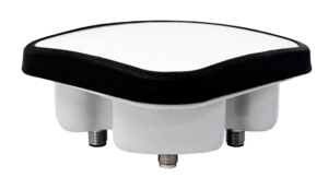
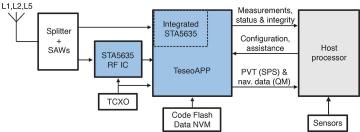
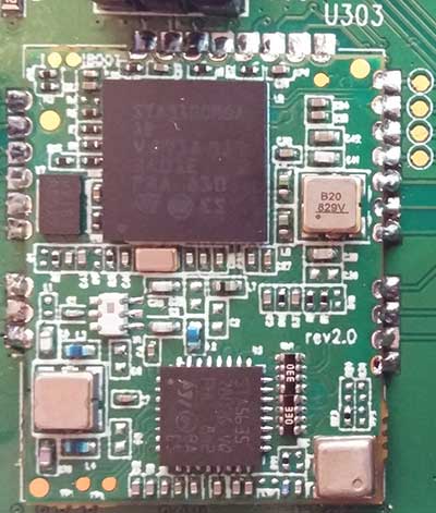
The target architecture for a safety-critical platform is sketched in FIGURE 1, where a host microprocessor is in charge of collecting GNSS observables and sensor data from the TeseoAPP. The latter includes on the same chip die a first configurable RF chain for the L1 signal ensemble and the baseband part for processing all the signals in the served bands, while the second chip is an RF front end (code-named STA5635), configurable for receiving the other served bands (such as GPS L2 or L5, Galileo E5a or E5b or E6, and so forth). The two chips are clearly visible in the photograph of a TeseoAPP evaluation module of FIGURE 2.
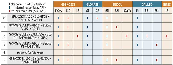
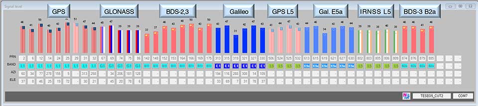
The selected frequency plan and constellation configuration depend on the specific autonomous driving scenario and the target geographic area. The TeseoAPP supports a mix of frequencies and signals as shown in TABLE 1. The chipset baseband unit can track up to 80 channels. A tracking snapshot from a rooftop antenna (located at the ST office in Naples, Italy) is illustrated in FIGURE 3.
Both the TeseoAPP and the STA5635 have been designed for ASIL-B following the concept of “safety element out of context” (SEooC) described in ISO standard ISO 26262:2012. In this context, assumptions have been made for the application (such as on the mission profile), identifying the related safety goals from which functional and technical safety requirements have been derived.
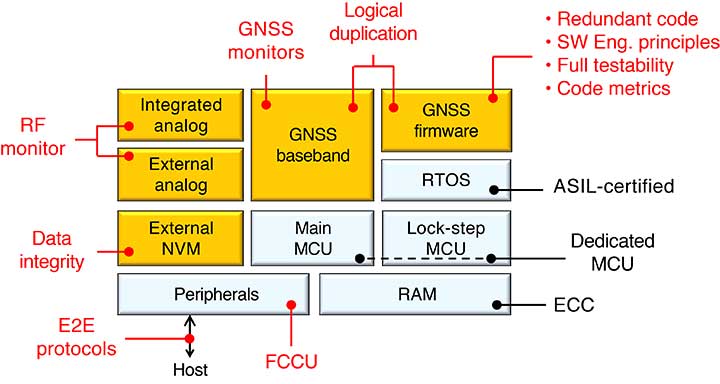
Following the guidelines identified in the ISO 26262 flow for safety-relevant product development, several safety mechanisms have been identified at the hardware, firmware and system/boot level. The microcontroller unit (MCU) supports dual-core operation in a lock-step configuration to verify processor output errors together with a memory built-in self-test (executed at startup) and error correction code on a safety-related embedded random access memory. Other hardware redundancies have been introduced in safety relevant parts such as triple-voted registers for critical configuration parameters. For the real-time operating system (RTOS), an ASIL-D-level product — the highest level — was selected. Functional safety analysis of the GNSS sub-system has produced a dedicated technical safety concept, including aspects such as tuner operation, interference and jamming mitigation, signals and observables quality management (QM), reliable host communication (using generic end-to-end or E2E protocols for data integrity and resilient flow control), and reliable system software. A simplified overview of all these safety mechanisms is outlined in FIGURE 4, where the orange-colored blocks are specific for the GNSS sub-system.
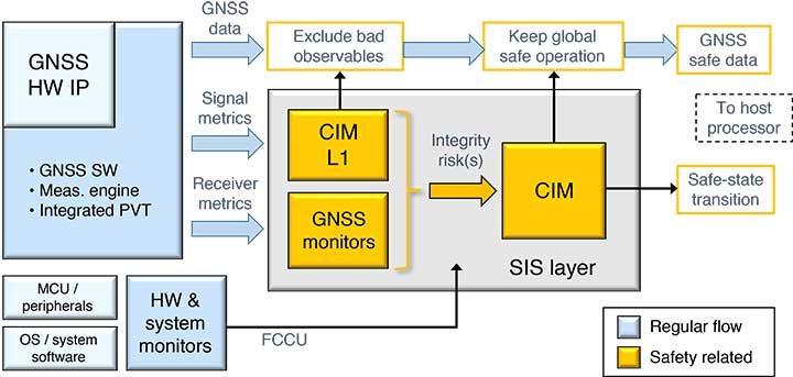
Safety Mechanisms. The technical safety concept of the GNSS sub-system is implemented by a security, integrity and safety (SIS) monitoring layer (see FIGURE 5). The SIS collects information and metrics from other receiver blocks embedded in the RF/baseband hardware and from different components of the GNSS firmware stack. The SIS internally computes integrity risk estimates, which are delivered to a central intelligence monitor (CIM) capable of switching the receiver into a safe state, within a fault-tolerant time interval, when the overall receiver integrity appears compromised. In its simplest form, the CIM can be represented by a weighted sum of integrity risk inputs, followed by some activation function. During this process, a first layer of logic (CIM-L1) combines a subset of signal quality metrics to decide a priori which observables shall be passed to the host or discarded (not delivered).
The collected signal metrics include quality estimators (based on multi-correlation techniques for example) or classic linear combinations of observables (such as dual-frequency carrier-phase differences or code-minus-carrier). Receiver metrics, on the other hand, have a more global scope and include estimators for inter-frequency biases, system-time cross-checks among constellations, and so on. The fault collection and control unit (FCCU) conveys hardware status flags to the SIS. Typically, an FCCU exception indicates some critical hardware failure and takes a priority path when switching the safe state. For example, a fault in the MCU lock-step monitor will trigger an immediate firmware action, mediated by the FCCU.
POSITIONING PERFORMANCE
To demonstrate the performance that can be achieved using the ST TeseoAPP chipset, Hexagon Positioning Intelligence (PI) has combined measurements from the TeseoAPP with an automotive-grade antenna and Terrastar-X correction technology, and processed the data using Hexagon PI’s software positioning engine. Even with a modern receiver supporting dual-frequency, multi-constellation measurements, such as the TeseoAPP, corrections are necessary to deliver decimeter-level performance and safety information required by an autonomous vehicle.
In clear-sky environments, lane-level positioning accuracy is achieved, enabling GNSS as a key input to autonomous systems. FIGURE 6 shows the horizontal error performance of the combined ST+PI solution in the form of an error time series and an error cumulative distribution function (CDF). The error performance expected from today’s single frequency automotive-grade GNSS without corrections and processing is also shown for comparison.

For guidance systems in autonomous applications, the GNSS position must be accompanied by safety information and integrity guarantees. The concept of protection levels (PLs) has been introduced to provide this. A horizontal protection level defines a circle or ellipse around the reported GNSS position, which will have some error, within which the actual position is guaranteed to fall. The Hexagon PI software positioning engine is ASIL-B rated, so its position and PL outputs are available for use in safety-related autonomous applications. The autonomous system using the GNSS position is assured that its actual position is within the protection level ellipse. To output ASIL-B-rated positions accompanied by PLs, ASIL-rated GNSS measurement inputs are required.
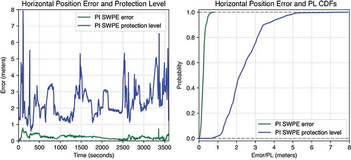
Using the inputs and techniques described above, the Hexagon PI software positioning engine calculates PLs for every GNSS position output. The Hexagon PI data from Figure 6 is shown again in FIGURE 7 with accompanying PL information. In this case, a PL with integrity risk of 10-7 is shown, meaning that the actual position error is expected to exceed the reported PL at a rate less than 10-7 per hour.

The PLs shown in Figure 7 are typically much greater than the position error. This is because the protection level calculation must account for a large number of potential faults that are not generally present. For instance, undetectable GNSS satellite faults can occur at rates greater than 10-7 per hour, and so must be accounted for in the PL.
In non-clear-sky environments, the GNSS position calculation is complicated by frequent loss of “sight” of the GNSS satellites. This is mitigated by having additional constellations and frequencies. However, for added availability of a precise position in challenging environments, it is necessary to incorporate sensor fusion into the position calculation, typically by using a six degree-of-freedom inertial measurement unit (IMU) as input, which includes three accelerometers and three gyroscopes to measure 3D translational and rotational motion. The IMU can maintain position accuracy for short periods when GNSS is unavailable, such as when driving under an overpass on a highway. The IMU provides a relative positioning output, so the absolute error growth is unconstrained in the absence of GNSS inputs. Therefore, it is important to have the GNSS receiver as the primary sensor in the positioning solution to constrain IMU drift and to reacquire GNSS signals rapidly after emerging from a GNSS outage.
Position error results for a typical highway environment are shown in FIGURE 8 after adding input from an automotive-quality IMU to the Hexagon PI software positioning engine. Small spikes in position error are due to short GNSS outages along the test route. However, the error growth due to loss of GNSS is minimal due to the coupling of the IMU data with the GNSS measurements.
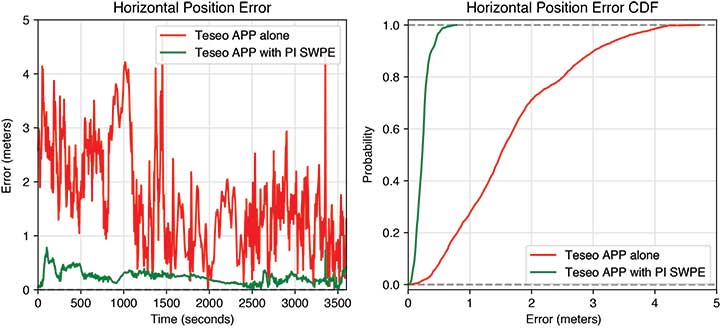
FIGURE 9 shows the Hexagon PI highway data with accompanying PLs. Though the errors are well-constrained through GNSS outages, the PLs typically increase significantly. This is due to the higher noise of low-cost IMUs, and the uncertainty associated with reacquiring GNSS signals. PLs must account for worst-case IMU performance, which can have errors orders of magnitude greater than the nominal performance. During GNSS signal reacquisition, minimizing receiver noise is critical for fast position reconvergence, reinforcing the need for high-quality GNSS in autonomous applications.
CONCLUSION
The TeseoAPP is the first generation of multi-band GNSS chipsets designed by STMicroelectronics to meet the two main requirements of autonomous driving: accuracy and safety-critical operation. The execution of the ISO 26262 standard for TeseoAPP is still a work in progress and encompasses two main aspects: 1) a safety plan implementation, code quality metrics and processes management and 2) the technical safety concept. Both of these aspects presented specific challenges, mainly due to the inherent complexity of the product and the large amount of firmware involved.
To exploit the maximum benefit of the TeseoAPP in safety-critical automotive applications, a high-accuracy ASIL-B-rated position engine is required. Hexagon PI’s software positioning engine is designed to use measurements from an ASIL-rated GNSS receiver, along with GNSS corrections and IMU data, to generate ASIL-rated position outputs, with accompanying integrity guarantees. The Hexagon PI software positioning engine computes protection levels. The calculation and determination of PLs is required to meet the safety and integrity guarantees necessary in autonomous driving for functionally safe operation. The software positioning engine also outputs ASIL-rated velocity, attitude and absolute time data, although we have not discussed these in this article.
The required high performance and safety expectations suggested, since the early stages of the project, a system composition in which the TeseoAPP was configured as an ASIL-B measurement-engine whereas the ASIL-B software positioning engine algorithms (by Hexagon PI) run on a separate ASIL host processor. We believe this synergy of competencies will represent the key for a successful solution to enable safe and reliable positioning in autonomous driving applications.
ACKNOWLEDGMENTS
The TeseoAPP chipset has been developed with the support and in the framework of the European Safety Critical Applications Positioning Engine project, which is funded by the European GNSS Agency under the European Union’s Fundamental Elements research and development program.
FABIO PISONI leads the GNSS System Architecture and Software Team (Automotive and Discrete Group) at STMicroelectonics Italy in Milan, where he has worked since 2009. He has a degree in electronics from Politecnico di Milano and has previous experience as a GNSS and digital signal processing (DSP) engineer.
DOMENICO DI GRAZIA is a GNSS signal senior staff engineer at STMicroelectronics Italy in Naples, where he has worked since 2003. He has a degree in telecommunication engineering from the University of Naples Federico II, holds patents in the GNSS area, and has previous experience in digital communications.
GIUSEPPE AVELLONE is in the GNSS System Architecture and Software Team (Automotive and Discrete Group) at STMicroelectonics Italy in Catania, where he has worked since 1998. He has a degree in electronics from Università di Palermo and previous experience as a GNSS and DSP engineer.
LUIS SERRANO is a GNSS technical marketing manager with STMicroelectronics based in Munich. He holds a Ph.D. in GNSS from the Department of Geodesy and Geomatics Engineering, University of New Brunswick, Canada. He has been active in the GNSS precise positioning field since 2007, and holds a patent on GNSS.
BRETT KRUGER is a software engineer specializing in GNSS/INS integration in the Safety Critical Systems Group at the Hexagon Positioning Intelligence (PI) NovAtel brand in Calgary, Canada. He holds an M.A.Sc. in electrical engineering from the University of Toronto, Canada.
LAURA NORMAN is a geomatics engineer specializing in GNSS integrity and protection levels in Hexagon PI’s Safety Critical Systems Group. She obtained her M.Sc. from the Department of Geomatics Engineering at the University of Calgary, Canada.
NATASHA WONG KEN is the Safety Critical Systems product manager at Hexagon PI. She has worked at Hexagon PI since 2012 after obtaining a B.Sc. in geomatics engineering from the University of Calgary.
FURTHER READING
- Standards for Vehicle Safety
“Keeping Safe on the Roads: Series of Standards for Vehicle Electronics Functional Safety Just Updated” by C. Naden, ISO, 19 Dec. 2018.
Road vehicles – Functional safety, ISO 26262:2018 (parts 1 to 12), International Organization of Standardization, Geneva, Switzerland, December 2018.
Failure Mechanism Based Stress Test Qualification for Integrated Circuits, AEC – Q100 – Rev-H, Automotive Electronics Council, 11 Sept. 2014.
- STMicroelectronics TeseoAPP (STA9100)
STA9100MGA, Automotive TeseoAPP (ASIL Precise Positioning) Family Multi Band GNSS Precise Measurement Engine Receiver, DB3546, Data Brief, STMicroelectronics, Geneva, Switzerland, 26 Feb. 2018.
- Future GNSS Automotive Positioning
“NovAtel Pioneers Autonomous Solutions with Positioning Engine, Corrections Services, Integrity Research” by T. Cozzens in GPS World, Vol. 29, No. 5, May 2018, pp. 33–34.
“Lane-level Positioning with Low-cost Map-aided GNSS/MEMS IMU Integration” by M. M. Atia and A. Hilal in GPS World, Vol. 29, No. 5, May 2018, pp. 18–32.
“Quo Vademus: Future Automotive GNSS Positioning in Urban Scenarios” by M. Escher, M. Stanisak and U. Bestmann in GPS World, Vol. 27, No. 5, May 2016, pp. 46–52.
- Precise Point Positioning
“Two Are Better Than One: Multi-frequency Precise Point Positioning Using GPS and Galileo” by F. Basile, T. Moore, C. Hill, G. McGraw and A. Johnson in GPS World, Vol. 29, No. 10, October 2018, pp. 27–37.
“More Is Better: Instantaneous Centimeter-level Multi-frequency Precise Point Positioning” by D. Laurichesse and S. Banville in GPS World, Vol. 29, No. 7, July 2018, pp. 42–47.
“Where Are We Now, and Where Are We Going? Examining Precise Point Positioning Now and in the Future” by S. Bisnath, J. Aggrey, G. Seepersad and M. Gill in GPS World, Vol. 29, No. 3, March 2018, pp. 41–48.
- Integrity of Automobile Positioning
“Expert Opinions: Integrity in the Vehicle Environment. Question: Why do we need to take integrity seriously in the vehicle environment?” by C. Rizos, R. Bryant and S. Pullen in GPS World, Vol. 28, No. 1, January 2017, p. 8.
“Integrity for Non-Aviation Users: Moving Away from Specific Risk” by S. Pullen, T. Walter and P. Enge in GPS World, Vol. 22, No. 7, July 2011, pp. 28–36.
“The Integrity of GPS” by R.B. Langley in GPS World, Vol. 10, No. 3, March 1999, pp. 60–63.