No audio available for this content.
By Jade Morton,
Guest Author
 After more than five years of hard work by 131 authors from 18 countries, the new book set Position, Navigation, and Timing Technologies in the 21st Century (PNT21) is finally ready to meet readers.
Published by Wiley-IEEE Press, PNT21 offers a uniquely comprehensive coverage of the latest developments in the field of PNT by world-renowned experts. The two-volume set contains 64 chapters organized into six parts.
Position, Navigation, and Timing Technologies in the 21st Century
Integrated Satellite Navigation, Sensor Systems, and Civil Applications
Y. Jade Morton, Frank van Diggelen, James J. Spilker Jr. and Bradford W. Parkinson, editors; Sherman Lo and Grace Gao, associate editors
Publisher: Wiley-IEEE Press
Hardcover Publication Date: January 2021
Vol. 1: ISBN: 978-1-119-45841-8, 1288 Pages
Vol 2: ISBN: 978-1-119-45849-4, 912 Pages
Volume 1 focuses on satellite navigation systems, technologies, and applications. It starts with a historical perspective on GPS and other related PNT development.
Part A consists of 12 chapters on fundamentals of and latest developments in global and regional satellite navigation systems (GNSS and RNSS), the need for their coexistence and mutual benefits, signal quality monitoring, satellite orbit and time synchronization, and satellite- and ground-based augmentation systems that provide information to improve the accuracy of navigation solutions.
Part B contains 13 chapters on recent progress in satellite navigation receiver technologies such as vector processing, assisted and high sensitivity GNSS, precise point positioning (PPP) and real time kinematic (RTK) systems, direct position estimation techniques, and GNSS antennas and array signal processing. Also included are the challenges of multipath-rich urban environments, handling spoofing and interference, and ensuring PNT integrity.
Part C finishes the volume with eight chapters on satellite navigation for engineering and scientific applications. A review of global geodesy and reference frames sets the stage for discussions on the broad field of geodetic sciences, followed by a chapter on GNSS-based time and frequency distribution. One chapter each is dedicated to severe weather, ionospheric effects and hazardous event monitoring. Finally, comprehensive treatments of GNSS radio occultation and reflectometry are provided.
Volume 2 addresses PNT using alternative signals and sensors and integrated PNT technologies for consumer and commercial applications. An overview chapter provides the motivation and organization of the volume, followed by a chapter on nonlinear estimation methods which are often employed in navigation system modeling and sensor integration.
Part D provides seven chapters devoted to using various radio signals-of-opportunity transmitted from sources on the ground, from aircraft, or from low Earth orbit (LEO) satellites for PNT purposes.
In Part E, eight chapters cover a broad range of non-radio frequency sensors operating in passive and active modes to produce navigation solutions, including MEMS inertial sensors, advances in clock technologies, magnetometers, imaging, lidar, digital photogrammetry, and signals received from celestial bodies.
A tutorial-style chapter on GNSS/INS integration methods is included in Part E. Also included are chapters on the neuroscience of navigation and animal navigation.
Finally, Part F presents a collection of contemporary PNT applications such as surveying and mobile mapping, precision agriculture, wearable systems, automated driving, train control, commercial unmanned aircraft systems, aviation, satellite orbit determination and formation flying, and navigation in the unique Arctic environment.
Table of Contents
Volume 1: Satellite Navigation Systems, Technologies, and Applications
- Part A: Satellite Navigation Systems
- Part B: Satellite Navigation Technologies
- Part C: Satellite Navigation for Engineering and Scientific Applications
Volume 2: Integrated Navigation Systems, Technologies, and Applications
- Part D: Position, Navigation, and Timing Using Radio Signals-of-Opportunity
- Part E: Position, Navigation, and Timing Using Non-Radio Signals-of-Opportunity
- Part F: Position, Navigation, and Timing for Consumer and Commercial Applications
Collective Goal. Because of the diverse authorship and topics covered in PNT21, the chapters were written in a variety of styles. Some offer high-level reviews of progress in specific subject areas, while others are tutorials. A few chapters include links to MatLab or Python example code as well as test data for readers who desire hands-on practice.
The collective goal is to appeal to industry professionals, researchers and academics involved with the science, engineering and application of PNT technologies. The website pnt21book.com provides downloadable code examples, data, homework problems, select high-resolution figures, errata and a way for readers to provide feedback.
Jade Morton is a professor at the University of Colorado Boulder and director of the Colorado Center for Astrodynamics Research (CCAR).
Jade Morton is a professor at the University of Colorado Boulder and director of the Colorado Center for Astrodynamics Research (CCAR).
Excerpt from PNT21
14.1 Anatomy of a GNSS Receiver
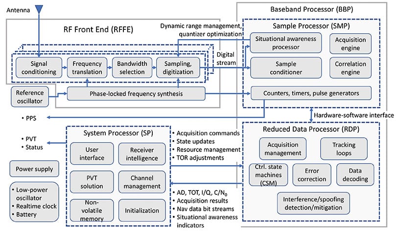
Irrespective of the receiver type, the functionality of all GNSS receivers can be broken down into three major blocks: RFFE, baseband processor (BBP), and system processor (SP). In the literature, the term “baseband processor” may be used to refer to the combination of both the BBP and SP defined here. The general anatomy of a GNSS receiver is shown in Figure 14.3.
The RFFE converts the signals induced at one or more antennas into digitized sample streams. Depending on the application and market segment, data rates for these streams may be as low as 0.4 Mbytes/s (e.g. L1 band sampled at 3.5 MSPS and 1-bit sampling in an asset tracking device) to greater than 3 GB/s (e.g. L1 and L2 bands sampled at 60 MSPS and 16 bits across seven elements in an anti-jam military GPS receiver).
The BBP performs digital signal processing to acquire and track GNSS signals present in the digitized sample streams to produce raw GNSS observables for each visible satellite. These observables include time of transmission (TOT), accumulated Doppler Range (ADR), signal quality metrics such as carrier-to-noise density ratio (C/N0), in-phase and quadrature prompt correlator output (I/Q), and raw symbols of a GNSS signal’s broadcast navigation message (which are subsequently decoded). In addition, modern receivers typically perform varying degrees of situational awareness processing to monitor in-band interference such that a level of confidence can be assigned to these raw observables. Some advanced receivers have the ability to identify spoofing signals. Depending on the application, situational awareness outputs may be as rudimentary as the automatic gain control (AGC) voltage used to adjust front-end amplification or as sophisticated as spectrogram, histogram, and sample statistics for all streams evaluated at full sample precision.
The BBP also contains a counter that is driven by a digital clock signal that is phase-locked to the receiver’s reference oscillator. This counter is the basis for the receiver’s clock and is used to generate time-of-reception (TOR) epochs. Raw observables for all satellites in view that lead to range measurements are computed with respect to TOR epochs. Since the receiver clock is based on its reference oscillator, it drifts with respect to GNSS system times. Although possible, the frequency bias, drift, and drift rate of the reference oscillator are typically not adjusted to align with GNSS system time because dynamic adjustment of the oscillator can lead to instabilities. Instead, these parameters are estimated and used to drive a separate adjustable-rate counter that compensates for the reference oscillator errors. This forms the basis for GNSS disciplined oscillators.
It is possible to partition all baseband processing into two categories: sample processor (SMP) and reduced-data processor (RDP). The SMP performs high-rate but simple and algorithmically regular operations which largely comprise multiply-accumulate operations performed at the sample rate. The SMP may also contain configurable timers and pulse/event generators that determine sample processing intervals, as well as output precise timing pulses that are synchronized down to the nanosecond level with respect to GNSS system times (timing accuracy and precision are dependent on the application and market segment). The RDP performs low-rate but algorithmically complex operations. Some representative software functions running within the RDP are illustrated in Figure 14.3.
Bidirectional communications occur between the SMP and RDP at regular timed intervals corresponding to a kilohertz rate. This rate is easily handled by all modern microprocessors. Since these SMP/RDP transactions are time critical, the RDP runs either bare-metal code (i.e. no operating system) or a real-time operating system. The operations within the BBP are inherently parallel and largely independent of each other at the signal processing level. Some coupling occurs, for example‚ in code-carrier aiding, inter-frequency aiding (see Chapter 15), inter-satellite aiding (referred to as vector tracking, described in Chapter 16), and multi-element processing. However, this coupling is typically implemented at higher levels of abstraction. Modern multi-band and multi-constellation receivers are capable of tracking hundreds of GNSS signals simultaneously. To facilitate this highly complex command and control structure – which also needs to be dynamically scalable and adaptive depending on the number of satellites in view, environmental conditions‚ and operating modes – the control architecture is typically layered (i.e. hierarchical). Control at the individual signal acquisition and tracking layers is performed using simple configurable finite state machines (FSMs) whose state transitions are based on signal condition indicators such as code lock, phase lock, C/N0, and code-carrier divergence (CCD). These FSMs operate independently but are typically managed at a high level by the SP.
The SP takes the raw signal observables produced by the BBP and transforms them to the standard GNSS receiver measurements. These measurements include pseudorange (PR), accumulated Doppler range (ADR), carrier phase (CP), carrier Doppler, and C/N0. All modern GNSS receivers also compute position, velocity, and time (PVT) at configurable rates (1 to 100 Hz depending on the receiver type). The SP encodes these in one or more industry-standard data formats for distribution. These formats include Receiver Independent Exchange Format (RINEX), the National Marine Electronics Association (NMEA) format, the Radio Technical Commission for Maritime Services (RTCM) format, and vendor-specific proprietary binary formats.
The SP also performs all high-level functions that include receiver initialization, channel management, and user interface functions. Unlike the BBP, the operations within the SP are generally not time critical. In modern GNSS receivers, the SP is often an embedded computer running an advanced non-real-time operating system. It may also support modern data interfaces (wired USB and Ethernet, or wireless/cellular connectivity) and an advanced graphical user interface with touchscreen support. While too numerous to mention, representative software processes running within the SP are illustrated in Figure 14.3.
Although not shown in Figure 14.3, modern receivers (or the navigation system to which they are interfaced) may also support aiding from external sensors such as inertial measurement units (IMUs), magnetometers, inclinometers, barometers, wheel sensors, RADAR, lidar, infrared (IR), and electro-optical (EO) sensors. This external aiding to GNSS can occur at three levels: loose coupling (position level), tight coupling (measurement level), or ultra-tight coupling (sampled signal processing level). GNSS aiding using various non-GNSS sensors is described in Chapters 43–51 in Volume II, Part E.
As shown in Figure 14.3, a stand-alone GNSS receiver contains battery-powered low-power circuitry to keep track of absolute time while it is turned off. A real-time clock (RTC) driven by a low-power crystal oscillator accomplishes this task. In some cases, this crystal may be the same as the reference oscillator. Knowledge of absolute time, along with the last known location and previously decoded almanac/ephemeris data stored in the receiver’s non-volatile memory, allows it to estimate satellites in view and their Doppler offsets, thereby significantly reducing the TTFF: the time needed to acquire satellites and produce the initial PVT solution. In the case of modern military receivers such as M-Code, or subscription-based services such as the Galileo Public Regulated Service (PRS), the receiver must acquire the cryptographically generated spreading code that may never repeat. In this case, the initial time uncertainty has a significant impact on the acquisition search space and consequently the computational resources consumed by the acquisition engine as well as power consumption. The TTFF can be dramatically reduced when absolute time, the satellites in view, their Doppler frequencies, and ephemerides are sent to the receiver from a nearby reference station via a communications link. This describes the basis of Assisted GNSS (A-GNSS) technology, covered in Chapter 17 of this book.
In some respects, the reference oscillator can be considered the single most important component that affects GNSS receiver performance. Although the PVT solution estimates the deterministic components of the reference oscillator’s frequency error (i.e. short-term bias, drift, and drift rate), the stochastic component cannot be estimated and hence represents additional dynamics that must be tracked (i.e. in addition to satellite motion, user motion, satellite clock motion, and any ionospheric scintillation and multipath). The bandwidth of the carrier tracking loops must be increased to accommodate this close-in phase noise of the reference oscillator. This in turn increases the variance of the range measurements. The reference oscillator is also the only “moving part” in the receiver since it is based on the resonance of a quartz crystal or microelectromechanical systems (MEMS) structure. In addition to microphonics, which are small phase variations that may occur within the RFFE due to external forces (particularly if the RFFE comprises large discrete components), these forces couple through the resonating element leading to shock and vibration sensitivity [6]. Similarly, thermal expansion of the crystal as well as analog components in the RFFE due to changing ambient temperature, unless appropriately compensated or isolated, causes temperature sensitivity. The frequency synthesizer in the RFFE multiplies the oscillator phase noise and dynamics by the ratio of the synthesizer output frequency to the oscillator fundamental frequency, thus placing a significant short-term stability requirement on the reference oscillator. Oscillator short-term stability limits the coherent integration time, which is proportional to the processing gain. Hence, the quality of the reference oscillator directly impacts the recever’s attainable sensitivity (i.e. the minimum observable signal levels) as well as the rate at which it can output statistically independent measurements. Oscillator effects are covered in detail in Chapter 47.
The receiver intelligence process within the SP shown in Figure 14.3 performs functions such as determining what satellites are in view, how best to mitigate any in-band interference (as observed by the situational awareness indicators), dynamically adapting to varying operating conditions, determining the best set of range measurements to use for the PVT solution based on optimum satellite geometry and estimated range error metrics indicated by C/N0 (for signal blockage) and CCD fluctuations (for multipath and ionospheric effects), and many such highly complex decisions. Typically, these high-level functions occur at a lower rate such as 1 Hz or less. To a large degree, the level of sophistication and engineering embedded within the receiver intelligence block, as well as the other low-level control functions determines the receiver’s performance in the real world, as expressed by established figures of merit. These include measurement accuracy, update rate, TTFF, sensitivity, dynamics handling capability, multipath mitigation performance, interference detection and mitigation capability, receiver autonomous integrity monitoring, and fault detection and exclusion (see Chapter 23). In other words, for a given market segment and its associated SWaP-C constraints, the receiver’s hardware and available signal processing capabilities can only do so much. The rest, and quite often the attributes that distinguish it in the marketplace, lies within the hundreds of thousands of person-hours and centuries of combined experience baked into its sophisticated software/firmware.