No audio available for this content.
A GPS-like ground-based technology teamed with inertial measurement and driving robots to deliver the necessary accuracy when obstructions knocked out GPS as a reliable sole sensor.
By David Aylor, Insurance Institute for Highway Safety
Andrew Pick, Anthony Best Dynamics Ltd.
Paris Austin and Martin Parry, Oxford Technical Solutions Ltd.
Consumer information organizations like the Insurance Institute for Highway Safety (IIHS) design test procedures to compare different automobile manufacturers’ safety systems. The test equipment must be repeatable and as independent as possible of time of day, weather conditions or test-driver behavior.
In 2015 IIHS completed a $30 million expansion of the Vehicle Research Center (VRC), its centerpiece a 5-acre fabric-covered track, to allow testing to continue rain or shine. It is complemented by an outdoor track for a total area of 15 acres.
IIHS rates crash prevention systems such as Forward Collision Warning (FCW) and Automatic Emergency Braking (AEB), and looks at how well those systems can identify road users like pedestrians and bicyclists.
To simulate real-life potential crashes for safe, accurate and repeatable testing, the Institute has been researching robotic equipment to automate some of the driving tasks.
While the covered track offered much needed all-weather testing capability, it introduced a challenge for the standard high-accuracy GPS/GNSS equipment used for testing. IIHS operates a multi-frequency GNSS base station with real-time corrections. High-accuracy position, velocity and time (PVT) and other relevant parameters from these GPS units are required for testing and are essential for operating robotic test equipment.
However, tests on the covered track clearly showed the equipment was not delivering the required accuracy, reliability and repeatability: the steel trusses of the covered track roof were a sufficient obstruction to GNSS signals.
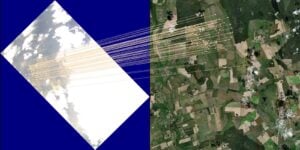
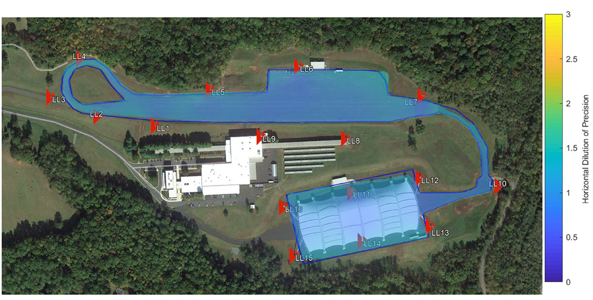
Locata. Locata provides an RTK GPS-like positioning capability utilizing ground-based transmitters which precisely time-synchronize to one another using their proprietary ranging signals without the need for cables or atomic clocks. This delivers centimeter-level accuracy with very high reliability, in networks of strategically placed, static LocataLites (LLs).
The IIHS Locata network was deployed with 16 LLs covering both open and covered test tracks (Figure 1). The network meets two key requirements: accuracy of 10 cm or better at 95% confidence and a very high degree of repeatability with a service availability (defined as meeting the above requirement) of better than 95% of the time.
AB Dynamics. Anthony Best Dynamics supplies driving robots for the design, development and testing of automotive technology. Driving robots precisely and accurately control the vehicle steering wheel, brake and throttle pedals with a level of repeatability that vastly exceeds that achieved by human test drivers. When coupled with an accurate position measurement sensor the possibility of centimeter accurate path-following control becomes reality.
In ABD path-following control software, motion data is collected from a Locata/INS integration unit at 100 Hz and fed back to the robot’s path-following controller. The path-following controller employs a speed-dependent look-ahead algorithm that not only maintains the vehicle heading but allows centimeter-accurate path control.
OxTS. Oxford Technical Solutions specializes in the design and manufacture of GNSS-aided inertial navigation systems (GNSS/INS) for automotive testing.As well as one-centimeter position accuracy, OxTS systems measure movement in all vehicle-axes at up to 250 Hz.
Systems that only rely on inertial measurements are also prone to drift with time, so OxTS products are GNSS-aided; several other inputs can be used alongside the inertial measurement platform to create a hybrid system where each technology mitigates weaknesses in others.
The Locata network and associated receivers are configured to use the same time and coordinate frame as GPS so the measurements are identical to that of a GPS receiver. The OxTS system then uses this information as it would normally and is able to output accurate and reliable vehicle measurements while maintaining excellent position accuracy.
Measurements can be utilized by other equipment such as driving robots or logged for post-processing. Raw measurements are also logged internally so the data can be downloaded and reprocessed post-test, to test different scenarios or make other changes.
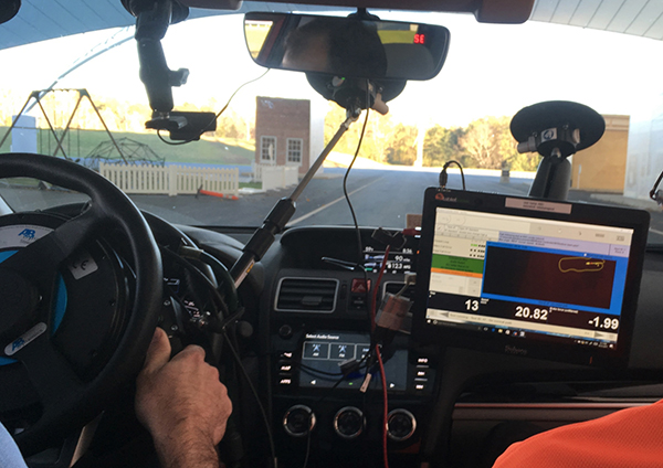
The driving robots have steering and pedal actuators that can be quickly installed without the need to make modifications to the vehicle as shown in Figure 2. Even with the robots installed, the steering wheel, throttle and brakes remain accessible to a human driver. At the heart of the robot is a dedicated real-time controller, which coordinates the steering and pedal robots and captures data at 1000 Hz.
Locata and OxTS units were installed in a rear passenger seat. The Locata antenna was roof-rack-mounted on a ground plane, approximately aligned with the centerline of the vehicle. The roof rack contained a second Locata antenna connected to a second Locata receiver. This was used for post-processing accuracy analysis of the fixed baseline (distance) between the two Locata antennas.
Test procedure
The automation kit enables the vehicle to be driven in manual mode and record scenarios for later replay. Drive scenarios can also be created in the user interface using basic geometric shapes and designate start, end or special maneuvering points within drives.
A local two-dimensional coordinate frame can be created with or without alignment to a global coordinate system. Each scenario may be replayed at various speed settings. For instance, most scenarios described later were replayed multiple times at different speed settings, often incrementing in fixed steps from a low speed such as 10 Km/hr.
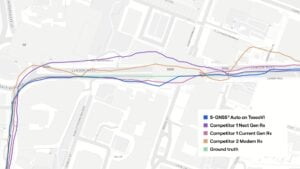
The demonstration platform was driven in various driving patterns on both test tracks. Figure 3 shows these patterns as a map derived from reported vehicle positions during the repeats of each scenario.
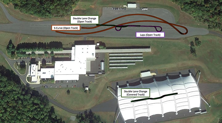
The Double Lane Changes (DLCs) conducted on both tracks resemble the driving pattern needed for testing most collision-avoidance and lane-change features. The S-curve is a driving pattern used for the IIHS headlight evaluations.
Analysis and results
Data analysis was focused on characterizing the accuracy and repeatability of the automated test setup as a complete system first and then Locata alone as the core positioning system. As the first step, data from two full days of testing were reduced to repetitions of the various driving patterns shown in Figure 3. Start and end times of each repetition were extracted from AB Dynamics systems and corresponding Locata system data was further processed to generate the results shown here.
The foundation for highly repeatable control system and positioning accuracy is to have a highly reliable network that delivers repeatable DOPs and number of ranging signals at any given track location. Repeatability of the numbers of LLs seen and the HDOPs were investigated for this purpose. Shown in Figure 4 is the actual number of LLs observed and the resulting HDOP during the five repeats of the DLCs done at 45 km/h in the covered track.
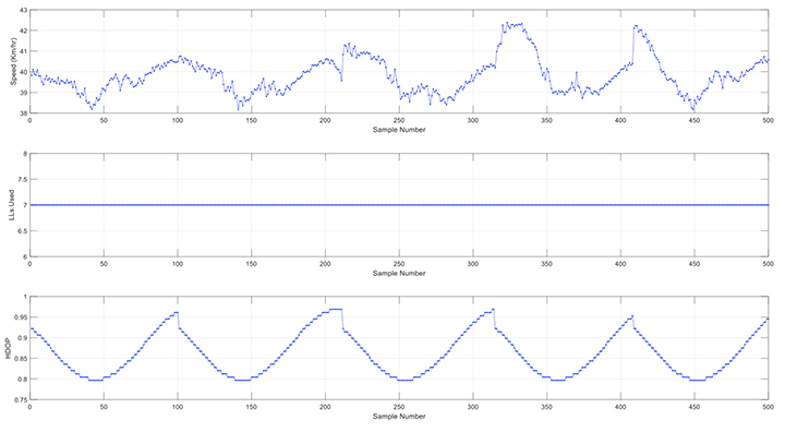
The number of LLs used remain constant at seven as expected and the HDOP change resulting from the motion repeats for each of the repetitions. Shown in Figure 5 are similar plots for the seven repetitions of the Lap scenario done at 20 km/h in the open track. In these, the LLs used vary between 8 and 9, with the drop happening at one end of the lap. Although slight variations can be seen in the times of the drops due to the varying speed of the vehicle during the turns, the HDOP pattern repeats consistently for all seven repetitions.

Analysis of the 48 DLC repetitions from the covered track is presented in Figure 6. Locata position data from all repetitions were averaged along the drive path to estimate a best fit path and the deviation from this was estimated (top subplot). The best fit path allows the estimation of the run-to-run deviation of the vehicle path. The middle subplot shows the mean and standard deviation of cross track error (or spread) of all the repetitions compared to the best fit path.
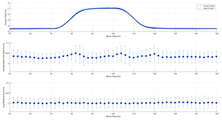
Despite the 48 DLC repetitions being carried out across a range of speeds (10-45 km/h) a high level of repeatability was measured. In straight segments the control system was able to repeat all the runs with below 4 cm of mean deviation from each other. This increases to 5 cm during turns due to the increasing lateral acceleration at higher speeds. The standard deviation also follows the same pattern, remaining below 3 cm during the straight-line segments and increasing up to 5 cm during the turns. The bottom plot shows the mean and standard deviation of the baseline error measured between the two Locata antennas on the vehicle.
Locata baseline error from repetitions of all scenarios were then used to estimate a probability distribution function (PDF) to assess the Locata positioning system performance alone. This included close to 180,000 data points from around 5 hours of automated driving in various parts of the IIHS tracks. Resulting PDF is shown in Figure 7.
![FIGURE 7. [Brown] Locata position accuracy ±3 cm (95%) using the fixed baseline between two independently operating antenna-receiver pairs in the vehicle (5 hrs of automated driving on both tracks). [Blue] ABD system repeatability ±6 cm (95%) using across track error from 48 repetitions of the Double Lane Change maneuver on the Covered Track. (Figure: D. Aylor, A. Pick, P. Austin and M. Parry)](https://www.gpsworld.com/wp-content/uploads/2018/08/Figure7_chart-W.jpg)

Conclusion
The IIHS, one of two organizations in the United States that issue public crash safety ratings, is using Locata, a GPS-like local positioning system, under a canopy-covered test track that doesn’t have RTK-capable GNSS signal visibility.
Precise positioning from Locata integrated with INS by OxTS demonstrates automated path following with centimeter-level repeatability using driving robots from AB Dynamics. The authors thank and acknowledge the Locata team for the excellent support provided throughout the project.