No audio available for this content.
Constellation completed
By Peter Steigenberger, Steffen Thoelert, André Hauschild, Oliver Montenbruck and Richard B. Langley

POP QUIZ: What is the most populous metropolitan area in the world? According to Wikipedia, it is Tokyo. In fact, Japan has three cities in the list of the 50 largest cities in the world. Not only are there a lot of people in these cities, they also have many tall and densely packed buildings. And that’s a problem for GPS and the other global navigation satellite systems.
Radio signals travel in straight lines. Well, mostly so. At very low frequencies, radio waves propagate as ground waves and can achieve long-distance propagation in the waveguide formed by the surface of the Earth and the ionosphere. At slightly higher frequencies, such as those used by AM radio, signals still travel as ground waves. However, additionally, the signals propagate upwards as skywaves. During daylight hours, the D layer of the ionosphere absorbs the skywaves, but when the D layer dissipates at night, the higher ionospheric levels can reflect skywaves back to Earth allowing long-distance reception. And communication by shortwave is virtually all by ionosphere-bounce skywaves. Above 30 MHz or so, signals normally travel along line-of-sight raypaths. The atmosphere can slightly bend the raypath, but the signals essentially travel in straight lines. Of course, that’s what makes GPS possible.
GPS works exceedingly well as long as a receiver’s antenna has a line-of-sight “view” of the satellites. Obstacles such as mountains and buildings block the relatively weak GPS signals. In concrete canyons, for example, that may leave a receiver with fewer than four satellites in view, meaning that 3D positioning is impossible. Even if four or more satellites are visible, they may be bunched together in the sky, resulting in high dilution of precision values and potentially large position errors.
In an effort to alleviate the GPS positioning problem in both urban and mountainous areas of Japan, the Japanese government has developed the Quasi-Zenith Satellite System (QZSS). A constellation of three inclined geosynchronous orbit (IGSO) satellites and one geostationary satellite transmits GPS-compatible signals to enhance positioning availability and accuracy. The IGSO satellites have repeating figure-eight ground tracks with the satellites spending most of their one-sidereal-day orbit, centered around apogee, over the Japanese archipelago. The satellites sequentially hover in the sky near the zenith for long periods of time. The satellites also provide both standard and advanced augmentation signals.
The first, or prototype, Block I QZSS satellite was launched in 2010 and, based on the positive test results from this satellite, an additional three satellites were launched in 2017, completing a four-satellite constellation. In this month’s column, we examine the recent developments of this unique and innovative navigation system.
With the launch of two additional spacecraft in August and October 2017, the Japanese Quasi-Zenith Satellite System (QZSS) reached the goal of a four-satellite constellation with the first fully-operational services expected to start in 2018. Aug. 19, 2017, marked the launch of QZS-3, the first geostationary Earth orbit (GEO) QZSS satellite, while the third spacecraft in inclined geosynchronous orbit (IGSO), QZS-4, was subsequently launched on Oct. 10, 2017. An artist’s view of the constellation is shown in FIGURE 1.
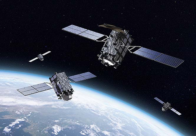
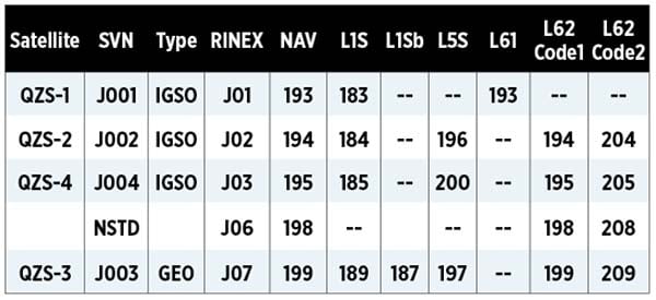
Table 1 lists the four satellites of the current QZSS constellation. Whereas the first generation Block I satellite QZS-1 was launched in 2010, the three Block II satellites joined the constellation in 2017.

The most obvious visual difference between the QZSS Block I and II satellites is the different number of subpanels for the solar arrays: three for the Block I satellite and two for the Block II satellites with spanned widths of 25.3 meters and 19.0 meters, respectively. The reduced size of the Block II array has been achieved through the use of new, high-efficiency solar cells. The GEO satellite in addition carries S- and Ku-band antennas with diameters of 3.2 meters and 1.0 meter, respectively. While the IGSO satellites are equipped with a helix antenna array for transmission of the main L-band navigation signals, the GEO satellite uses a patch antenna array similar to that of the Galileo satellites.
The ground tracks of the four QZSS satellites are plotted in FIGURE 2. The ground tracks of all of the IGSO satellites have the characteristic figure-eight shape due to the large orbit eccentricity of 0.075 and results in a longer visibility period for users in the northern hemisphere. The ground tracks do not precisely match, however. QZS-1 and QZS-4 have similar orbit inclinations (with respect to the equator) of 40.9° and 40.5°. QZS-2, on the other hand, has a larger inclination of 44.5°, which leads to a wider extension of the ground track in the north-south direction.

Also, the central longitude of the ground tracks, which marks the center of the figure-eight shape, varies between 130° and 140° E. These differences are still within the tolerances defined in the QZSS Interface Specification, version 1.8 of Oct. 3, 2016, which specifies the inclination to be 43° ± 4° and the central longitude of the ground track to be 135° ± 5° E. The GEO satellite QZS-3 is located at 127° E and has been controlled to stay within a 0.1° inclination window since achieving its initial orbit.
All QZSS satellites transmit navigation signals in the L1, L2 and L5 bands compatible with GPS, namely L1 C/A, L1C, L2C and L5 (the Positioning, Navigation and Timing or PNT service). QZSS-specific signals are transmitted in the L1, L5 and L6 bands: the Sub-meter Level Augmentation Service or SLAS (formerly, Submeter-class Augmentation with Integrity Function or SAIF) signals for all satellites on L1 and, in addition, on L5 for Block II satellites (see TABLE 2).
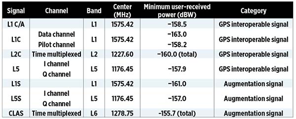
Starting in 2020, the GEO satellite will also provide a satellite-based augmentation system (SBAS) signal called L1Sb with range corrections and integrity information for aviation applications in particular. The SLAS and SBAS signals are transmitted via dedicated antennas but they are phase coherent with the GPS-compatible navigation signals transmitted via the main L-band antenna. The L6 signal provides the Centimeter Level Augmentation Service or CLAS (formerly, the L-band Experiment or LEX) on all QZSS satellites, but employs a different signal structure for Block I (L61) and Block II (L62). An overview of the various L-band signals and corresponding PRN assignments is given in TABLE 3. QZS-3 also provides the QZSS Safety Confirmation Service (Q-ANPI) to support rescue operations with S-band communication in case of a disaster. The total transmit power is 500 watts for the Block II IGSO satellites and 550 watts for the GEO satellite.
QZS-3/4 SIGNAL TRANSMISSION
Tracking of the QZS-3 L1 C/A and L5 signals by receivers in the German Aerospace Center (Deutsches Zentrum für Luft- und Raumfahrt or DLR) and International GNSS Service networks started on Sept. 10, 2017, at 09:04 UTC followed by the L1C and L2C signals at 09:27 UTC. L5 tracking started with a very low carrier-to-noise-density ratio (C/N0) of 10 – 20 dB-Hz that increased to 50 – 55 dB-Hz shortly after the activation of the L1C and L2C signals. QZS-3 broadcast ephemerides were first transmitted on Oct. 4, 2017, at 16:00 UTC. However, tracking of the L1, L2 and L5 navigation signals with common geodetic receivers is currently limited to receivers with experimental firmware versions developed by three different manufacturers.
Signal transmissions from QZS-4 started on Nov. 1, 2017. The first L1 C/A signals of PRN J03 were received at 02:50 UTC. At the same time, L5 signal transmission started but this signal was only tracked by a very limited number of receivers due to its low signal strength resulting in a C/N0 of only about 15 dB-Hz. At 03:14 UTC, an increase of the C/N0 by about 40 dB occurred and many additional receivers started tracking the L5 signal. At the same time, the L1C and L2C signals were also activated followed by the L1 SLAS signal at 03:20 UTC.
It is interesting to note that QZS-4 also transmitted the non-standard code J06 on different frequencies during its first weeks of operation. This code cannot be used for positioning and is used for test purposes or in case of system errors. Until Nov. 27, 2017, QZS-4 regularly switched between transmission of standard and non-standard codes. An example of such a switch for the station UNX200AUS located in Sydney, Australia, is shown in FIGURE 3. During this test period, several outages of individual or all navigation signals also occurred. Since Nov. 24, 2017, 5:00 UTC, broadcast ephemerides of QZS-4 have been available and transmission of the L5 SLAS signal started at 09:31 UTC.

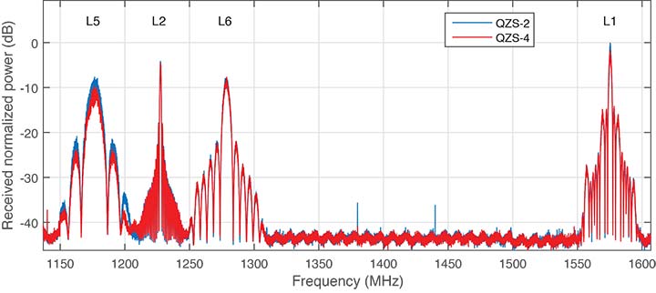
FIGURE 4 shows the L-band normalized power spectra of QZS-2 and QZS-4. The spectra were obtained from in-phase (I) and quadrature (Q) data recorded with DLR’s 30-meter high-gain antenna in Weilheim, Germany. Almost identical characteristics can be seen for the signals of both satellites in the L1, L2 and L6 bands. However, in the L5 band, QZS-4 shows a slightly lower power than that of QZS-2 due to the lack of the L5 SLAS transmission during the data recording. Unfortunately, QZS-3 is not visible from Weilheim due to a longitude difference of more than 115°.
ATTITUDE
Usually, QZS-2 and QZS-4 follow a nominal yaw steering attitude with the spacecraft z-axis pointing towards the Earth and the y-axis (solar panel axis) oriented perpendicular to the plane defined by the locations of the satellite, the Sun, and the Earth. The maximum yaw rate of these satellites is limited to 0.055° per second and can be exceeded by the nominal yaw rate when the angle of the Sun with respect to the orbital plane (the beta angle, β) is between -5° and +5°. During orbit control maneuvers, the QZSS Block II IGSO satellites are operated in orbit normal mode with the z-axis pointing to the Earth and the y-axis perpendicular to the orbital plane. The geostationary QZS-3 satellite is continuously operated in orbit normal model while QZS-1 enters orbit normal mode for |β| < 20°.
Detailed information about the different attitude rules as well as spacecraft reference frame, mass, center of mass, phase center offsets and variations of the navigation antenna, laser retroreflector offsets, satellite group delays as well as the total transmit power of all four satellites is provided by the Cabinet Office, Government of Japan, in the QZSS satellite information documents.
Since all QZSS satellites are equipped with a separate L1 SLAS transmit antenna, which is mounted with an offset to the main L-band antenna, each satellite’s attitude can be directly estimated from single-difference carrier-phase observations between the two spacecraft antennas.
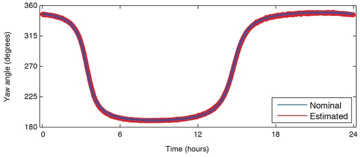
FIGURE 5 illustrates the attitude of QZS-4 estimated from L1 C/A and L1 SLAS observations from 10 tracking stations as well as the nominal yaw steering attitude. QZS-4 had a beta angle of about 11° on Dec. 9, 2017, confirming that this satellite does not enter orbit normal mode for |β| < 20° as does QZS-1. Differences between nominal yaw steering attitude and estimated attitude are usually within ±1.5° reflecting estimation errors as well as differences between nominal and true attitude.
CLOCK PERFORMANCE
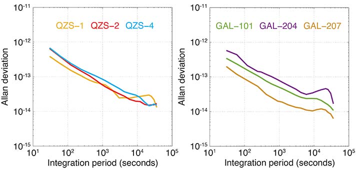
The clock stability represented by the modified Allan deviation is given in the upper panel of FIGURE 6 for the QZSS IGSO satellites. The QZSS Block II IGSO satellites show an almost identical stability for integration periods up to 100 seconds. For longer periods, the QZS-2 clock seems to perform slightly better.
However, this effect is probably related to the number of stations contributing to the clock solutions of the individual satellites which differs by a factor of more than two. For comparison purposes, the Allan deviation of two Galileo rubidium clocks (GAL-101 and GAL-204) and a Galileo passive hydrogen maser (PHM, GAL-207) are plotted in the bottom panel of Figure 6.
Whereas the performance of the QZSS and Galileo rubidium clocks is very similar, the Galileo PHM is more stable by a factor of two to five over all integration periods.
CONCLUSIONS
With the launch of the third IGSO spacecraft and the first GEO spacecraft, the QZSS constellation has reached a four-satellite configuration, which is required for the provision of operational augmentation services. QZS-3 and QZS-4 were declared useable for PNT, SLAS, and CLAS trial services on Dec. 18, 2017, and Jan. 12, 2018, respectively. Inclusion in the operational QZSS constellation is expected for 2018 and this will provide continuous visibility of three satellites in the service area. An expansion to a constellation of seven satellites is planned for 2023 including a Public Regulated Service for authorized users.
MANUFACTURERS
Data used in this article was collected using Javad GNSS Delta-G3TH, Trimble NetR9 and Septentrio PolaRx4 and PolaRx5 receivers.
Authors Peter Steigenberger, Steffen Thoelert, André Hauschild and Oliver Montenbruck are from the German Aerospace Center (DLR).
Richard B. Langley is from the University of New Brunswick and authors the monthly “Innovation” column for GPS World magazine.
FURTHER READING
• Quasi-Zenith Satellite System
“Quasi-Zenith Satellite System” part of “Regional Systems” by S. Kogure, A.S. Ganeshan and O. Montenbruck, Chapter 11 in Springer Handbook of Global Navigation Satellite Systems, edited by P.J.G. Teunissen and O. Montenbruck, published by Springer International Publishing AG, Cham, Switzerland, 2017.
• Interface Specifications
Quasi-Zenith Satellite System Interface Specification: Satellite Positioning, Navigation and Timing Service (IS-QZSS-PNT-001), Cabinet Office, Government of Japan, Tokyo, March 28, 2017.
Quasi-Zenith Satellite System Interface Specification: Sub-meter Level Augmentation Service
(IS-QZSS-L1S-001), Cabinet Office, Government of Japan, Tokyo, March 28, 2017.
Quasi-Zenith Satellite System Interface Specification: Centimeter Level Augmentation Service
(IS-QZSS-L6-001), Cabinet Office, Government of Japan, Tokyo, Sept. 15, 2017.
• Previous QZSS Signal Analysis
“QZS-2 Signal Analysis, QZS-3 Launched” by S. Thoelert, A. Hauschild, P. Steigenberger, O. Montenbruck and R.B. Langley in GPS World, Vol. 28, No. 9, September 2017, pp. 10–14.
• DLR’s 30-meter High-Gain Antenna in Weilheim
“GPS L5 First Light: A Preliminary Analysis of SVN49’s Demonstration Signal” by M. Meurer, S. Erker, S. Thölert, O. Montenbruck, A. Hauschild and R.B. Langley in GPS World, Vol. 20, No. 6, June 2009, pp. 49-58.