Listen to this content

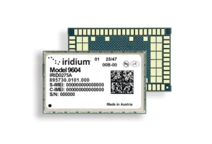
GLONASS remains a core of Russia’s positioning, navigation and timing (PNT) system and is utilized by people around the world. Annual shipments of new GLONASS/GNSS receivers for the communications, transport, agriculture and power industries exceed 25 million units in Russia alone. These users are interested in continuously increasing the quality of PNT primarily based on the improvement of the basic service radio navigation field generated by the GLONASS space complex.
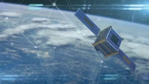
This space complex consists of the constellation comprising medium-Earth orbit (MEO) satellites, the modernized ground control complex and the ensemble of user equipment. The current constellation consists of 26 satellites comprising three generations and five modifications. For the past 15 years, GLONASS-M has been the core satellite and now the constellation includes 21 of them. The fact that 14 of them successfully function beyond their guaranteed active lifetime verifies their high reliability. They are steadily being replaced with GLONASS-K satellites, of which there are already four in the constellation. Along with GLONASS-K launches, the in-orbit testing of the first GLONASS-K2 satellite was initiated on August 7, 2023.
Since the launch of the first GLONASS satellite, the navigation signals have changed significantly. Initially, each of 24 GLONASS satellites transmitted the signals with its own separate carrier frequencies in the L1 and L2 bands (Figure 1). The total bandwidth of the registered GLONASS satellite network was 23.72 MHz in L1 band and 20.72 MHz in L2 band, respectively.


In 1995, the Russian Federation assumed obligations to protect the band used in radio astronomy in the search for extraterrestrial life. At the first stage (until 1998), the broadcast of the navigation signals in the carrier frequency channels 16-20 was terminated and the frequency channels 13, 14, 20 and 21 were used under exceptional circumstances (Figure 2). Then, all newly launched satellites transmitted the signals only in the frequency channels 0-12. By 2005, the total bandwidth of GLONASS satellites was reduced to 16.97 MHz in L1 band and 15.47 MHz in L2 band respectively (Figure 3).
Starting in 2005, GLONASS satellites have been using the frequency channels from -7 to +6 (Figure 4) to broadcast frequency division multiple access (FDMA) navigation signals. As a result, the upper limit of the GLONASS signal bandwidth in the L1 band dropped from 1620.61 to 1610.485 MHz and the lower limit went down from 1596.89 to 1592.953 MHz. The signal bandwidth in L2 band changed similarly.
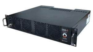
The GLONASS-K2 satellite was developed to improve GLONASS user performance. The satellite broadcasts new code division multiple access (CDMA) signals in the above mentioned bands as well as in the L3 band. The first satellite of this batch was successfully deployed in orbit on August 7, and already started to broadcast the new CDMA signals. The radio telescope of Bauman Moscow State Technical University is used to monitor the broadcast signals to analyze the frequency and power characteristics of the satellite.
The radio telescope has a large-aperture fully rotatable antenna with a dish diameter of 7.75 m. It ensures that the width of the main lobe of the antenna’s pattern in 1.6 GHz band is 1.8° and the power amplification of the received navigation signals is 40 dB.
Primarily, users are interested in the new CDMA navigation signal on L1OC transmitted along with the conventional signal on L1OF. The joint group bandwidth of the FDMA signals with the carrier frequency 1598.625 MHz, which refers to the frequency channel -6, and the CDMA signals with the carrier frequency 1600.995 MHz is shown in Figure 5.
The exploitation experience of recently manufactured satellites in practice demonstrates that their operational capacity exceeds their planned lifetime by one and a half times. The final GLONASS-M satellite (No. 761) launched in the last year was manufactured in 2015. These circumstances make it possible to predict that the renewal of the whole constellation with new GLONASS-K2 satellites broadcasting the full ensemble of CDMA signals is likely to be finished by 2035.
In 2024, the renewal of the constellation will continue due to the launches of GLONASS-K satellites and another GLONASS-K2 satellite.

With the launch of the first GLONASS-K2 satellite accomplished, the Passive Quantum-Optical System (PQOS) is implemented on the base of Russian quantum-optical systems with a wavelength of approximately 0.5 nm. The PQOS ensures pseudorange measurements in the optical band. The elements of the system include specialized ground equipment to register moments of laser pulse emission by a ground laser station (ground PQOS) and specialized satellite payload equipment to register moments of the laser pulse reception onboard (onboard PQOS). Therefore, all GLONASS new generation satellites are capable of performing both conventional active (two-way) measurements and passive (one-way) measurements with the accuracy of timescale difference definition better than a nanosecond and based on the data of laser optical systems.
The processing of active and passive measurements gives an opportunity to get their difference combinations to compare timescales kept by onboard and ground frequency standards at a previously unachievable picosecond level of precision. The accuracy of PQOS results is sufficient to provide in-orbit tests of prospective new generation onboard frequency standards with a daily stability σ around 5×10-15.
The achieved accuracy level of PQOS results is also sufficient to calibrate measurement links for prospective GLONASS satellites, including links of active measurement systems, inter-satellite links and ionosphere-free linear measurement combinations conducted by passive measurement equipment based on FDMA and CDMA signals. The obtained results correspond to the world accuracy level in metrology and ensure the uniformity of measurements. The developed PQOS and technologies based on its measurements fully contribute to the effective metrological support for the tests and operation of the GLONASS space complex, including prospective GLONASS-K2 satellites and the ground complex.