No audio available for this content.
GNSS robustness for unmanned aircraft systems
By Joshua Stubbs and Dennis M. Akos
When siting the antenna of a GNSS receiver or designing a GNSS-based navigation system, electromagnetic compatibility is an important concern. This is particularly true for airborne platforms. In this month’s cover story, we take a look at how radio-frequency interference can impact GNSS equipment on unmanned aircraft systems and how robustly the equipment can navigate those systems.

WHAT’S THE WEAKEST THING ABOUT GNSS? Literally, it’s the signals. The strength of GNSS signals is notoriously low as anyone who has tried to operate a consumer-level device inside a steel and concrete building can readily attest. Unlike mobile phone signals, GNSS signals are too weak to survive the attenuation of walls, floors, and ceilings and so typically cannot provide a dependable signal indoors for most receivers.
Even outdoors, the signals can be significantly attenuated by dense wet foliage and completely blocked by buildings and other objects. The GPS C/A-code signal generated by the transmitter in a satellite is approximately 27 watts. If such a transmitter were operated on Earth it would provide a decent signal even inside a nearby building. First responders, for example, can communicate with each other using portable transceivers with even lower-powered transmitters.
However, GPS satellites are about 20,000 kilometers away at their closest and the signals they transmit spread out as they travel to the Earth and even with the directivity of the satellite transmitting antenna, by the time the signals reach the surface of the Earth, their power density is only on the order of 10-13 watts per square meter. And that’s outdoors.
This signal is so weak that it is buried in the receiver’s background noise, which is similar to what you hear when you tune an AM radio between stations. So how can GPS possibly work with such a weak signal? The received signal is actually spread out over several megahertz of radio-frequency spectrum by the pseudorandom noise ranging code. It is this known noise-like code that allows receivers to determine the biased-ranges to satellites and from those ranges determine their positions. Knowing the code, the receiver de-spreads the weak received signal, concentrating it and lifting it above an acceptably low background noise.
All is fine and well as long as the received signal density doesn’t drop much below the 10-13 watts per square meter level but also the background noise level mustn’t rise much above the acceptable level for which the receiver is designed. Both of these criteria are reflected in the carrier-to-noise-density ratio, or C/N0, of the signal. Why might the noise level change? The noise comes from the receiver itself as well as from naturally produced electromagnetic radiation from the sky, the ground, and objects in the receiving antenna’s vicinity. The sky noise includes so-called cosmic noise from the sun, Milky Way galaxy, other discrete cosmic objects and radiation left over from the Big Bang as well as radiation from our atmosphere. For the most part, the noise from these sources is small but occasionally the sun can have a radio outburst that can significantly increase the noise level at GNSS frequencies and actually overpower the GNSS signals as happened with GPS in December 2006.
But the noise level can also be impacted by human-made electrical devices in the vicinity of a GNSS receiver’s antenna. This radio-frequency interference, or RFI, can come from devices such as radio transmitters, microwave ovens, motors, relays, ignition systems, switching power supplies and light dimmers. So, when siting the antenna of a GNSS receiver or designing a GNSS-based navigation system, electromagnetic compatibility is an important concern. This is particularly true for airborne platforms. In this month’s column we take a look at how RFI can impact GNSS equipment on unmanned aircraft systems and how robustly can the equipment navigate those systems.
As the number of unmanned aircraft systems (UAS; also called unmanned aerial vehicles and drones) in use is increasing across many sectors, there is an interest in understanding the robustness of the GNSS engine used on UAS. With UAS being integrated into the National Airspace System (NAS), questions arise about what kind of navigation system should be used on UAS, and to what degree it should be standardized. Conventional aircraft typically use a certified GNSS receiver for navigational purposes, and as UAS will share the sky with conventional aircraft in the future, it is not unreasonable that UAS will use similar receivers.
The first part of this article provides background on the status of GNSS standards for UAS. In the second part, we discuss why radio-frequency interference (RFI) can be expected on some UAS, together with what issues the RFI could cause for the GNSS engine. A simple experiment to determine the presence of RFI in the GPS L1 band due to proximity of a GPS antenna to electronics is presented in this section as well. The third part of the article discusses real-time kinematic (RTK) positioning for UAS purposes. In terms of accuracy, RTK positioning often provides the best results. The robustness of RTK measurements is questionable, though, because the technique relies on carrier-phase measurements. We present a case study, which shows some of the issues of using RTK positioning for UAS, in this part of the article, too.
GNSS standards for UAS
GNSS, and especially GPS, have been used in aviation for quite some time. The GPS receivers used for aviation have to guarantee a certain level of performance to be used, and are certified by the manufacturer to deliver said performance.
The Federal Aviation Administration (FAA) is working on integrating UAS into the NAS. The development of UAS has been quick and has led to a lack of standardization for UAS, something that does exist for traditional manned aircraft. This has led to operators in most cases having to file for exemptions from the existing rules in order to use UAS. It is the ambition of the FAA to transition from issuing exemptions to issuing certifications of UAS once an agreement on regulations has been reached. There are still a number of challenges associated with a full integration of UAS into the NAS, including regulatory, procedural and technical challenges.
The Wide Area Augmentation System (WAAS) was the first operational space-based augmentation system, intended to increase the robustness and reliability of GPS for aviation purposes. The WAAS Minimum Operational Performance Standards (MOPS) document (see Further Reading) specifies what kind of performance GPS plus WAAS provides to aviation users.
The MOPS requirements have been carefully examined and extended. The maximum in-band interference levels for aviation have been theoretically analyzed. As long as signal and interference levels are within the specified ranges, the required performance should be expected.
These levels, combined with the WAAS MOPS, provide the aviation community with the standardization required for manned aircraft operations where lives can be at stake if something were to go wrong with a navigation system. A Volpe National Transportation Systems Center report (see Further Reading) recommends the use of certified GPS receivers for applications where GPS is a critical system. This is not yet a requirement for UAS, and the question remains unanswered as to whether this will be a requirement for UAS in the future.
Traditional aviation uses required navigation performance (RNP), a performance-based navigation approach, to assess what type of navigation systems can be used for different phases of flight. For example, while an aircraft is en route, an RNP of 2 nautical miles is required, meaning the actual position of the aircraft cannot deviate more than 2 nautical miles from a reported position. It should be noted that RNP takes the entire system into consideration, from the space-segment to the receiver to the capabilities of the aircraft.
GNSS receivers used on manned aircraft have to be certified to deliver the RNP for each phase of flight for which they are used. Receiver autonomous integrity monitoring (RAIM) is used to ensure that faulty measurements do not affect the position and navigation solution. Due to the nature of RAIM, more satellites are required than the traditional minimum of four. If GNSS supplements other systems on board the aircraft, RAIM may be used to only monitor the quality of the system, and it will report when performance is below the required minimum. This form of RAIM requires a minimum of five satellites.
However, if the aircraft depends on GNSS for navigation, RAIM must be able to determine if a particular satellite is providing incorrect or subpar data. This requires one additional satellite, bringing the minimum number of satellites that have to be in view of the receiver’s antenna up to six (two more than non-RAIM GNSS operation).
However, using RAIM requires additional computational power, which one might not be able to provide on board a UAS due to size, weight and power limitations. It has been suggested that a GNSS system coupled with an inertial navigation system (INS) could be used for UAS navigation. A micro-electro-mechanical system (MEMS) INS would be very small, would not require a lot of power, and could improve the performance of a UAS navigation system. A GNSS plus MEMS INS approach may well be able to provide the robustness needed for UAS. However, the analysis of such a system is outside the scope of this article.
Some basic considerations should be taken into account for a UAS GNSS positioning system. Integrity should be prioritized over accuracy if the system is used for navigational purposes. Low-altitude operations could bring on problems of sky blockage. The proposed solution to this is to use a receiver capable of using multiple constellations to ensure that as many satellites as possible are in view.
Radio frequency interference
Radio frequency interference, or RFI, is the interference caused by electromagnetic waves interacting with a system they were not intended to interact with. A familiar case of RFI can be experienced when a cellular phone is placed in close proximity to an AM radio. A distinctive sound can sometimes be heard, which is the sound of RFI interacting with the radio.
Many forms of RFI exist. The interference can be in-band, that is, originating on frequencies transmitted within the band occupied by a desired signal, or out-of-band where the center-frequency of the interfering signal lies outside the band used by the desired signal but it can have a nonlinear impact on the components in the front end of the GNSS receiver. In some cases. the bandwidth of the interference is very small (narrowband), and in some cases the bandwidth is quite large (broadband). Depending on the type of interference, the affected systems will react differently.
RFI can, for obvious reasons, be expected from intentional radiators, such as equipment broadcasting signals near the GNSS signal frequencies, or other equipment that emits harmonics that lie close to the GNSS frequencies. These sources are documented, and the effects of them can be mitigated through proper planning and analysis.
However, electrical equipment can produce RFI that is not intended to be emitted — a so-called unintentional radiator. The Federal Communications Commission (FCC) Part 15 regulations define an unintentional radiator as “a device that intentionally generates radio frequency energy for use within the device, or that sends radio frequency signals by conduction to associated equipment via connecting wiring, but which is not intended to emit RF energy by radiation or induction.” Such devices are allowed to emit signal levels up to 300 or 500 microvolts per meter (depending on the class of the device) in the GNSS bands, as measured three meters away from the device.
Although most GNSS frequencies are protected, the risk for intentional or unintentional RFI exists. Some elements of the GPS system have been designed to mitigate interference effects, and GPS remains a relatively robust system. However, there are still sources that could interfere with the GPS signals, such as out-of-band transmissions, harmonics of airborne or ground-based transmitter equipment, radar transmitters or even local oscillators in nearby equipment.
In 1996, under a presidential decision directive, a commission to investigate a broad range of infrastructure vulnerabilities, including vulnerabilities to GPS, was set up. The commission found that GPS is in fact vulnerable to unintentional disruptions, from both human-made and naturally occurring sources. The commission recommended using certified GPS receivers for critical applications. The commission further recommended monitoring, reporting and locating unintentional RFI sources.
One of the potential issues with RFI in a GNSS engine is that it can cause false local correlation peaks, which could cause the code-tracking loop and the carrier-tracking loop to diverge from the main correlation peak.
RFI in the UAS GNSS Engine. On smaller UAS, space restrictions could lead to electronic components being placed in close proximity to each other. As stated earlier, some of these components could be producing RFI in the GNSS bands. If the RFI is strong enough to significantly raise the noise floor, the GPS signals could effectively be drowned out by noise. UAS that rely primarily on GNSS for navigation will risk losing navigational capabilities during such occurrences.
With no external interference present, the noise floor should be at the receiver’s thermal noise floor. The presence of interference could be indicated by the raising of the noise floor above the level of the thermal noise.
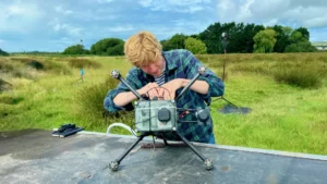
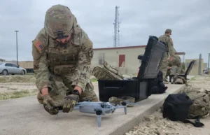
FIGURE 1 shows a simple setup for testing the hypothesis that electronics found on a common UAS could produce harmful RFI in the GPS engine. Some of the onboard equipment was a flight-controller, a 915-MHz communication link and a 2.4-GHz communication link.

A GPS antenna was placed outside and inside the UAS at common antenna locations. The antenna was connected to a high-performance GPS single-frequency-receiver evaluation kit and a spectrum analyzer. To enhance the effects and signals, a 40-dB inline amplifier was connected before the signal was split.
Three tests were carried out in this case study:
- In a reference test, the antenna was placed on the outside of the airframe and the UAS was not powered on.
- With the UAS power remaining off, the antenna was placed inside the airframe to see how much the signal was attenuated (see FIGURE 2).
- With the antenna still inside the airframe, the UAS was powered on and all systems on the UAS were running.

The results from the receiver can be seen in FIGURES 3 and 4. Figure 3 shows that the number of satellites being tracked by the GPS receiver did not change between tests.


However, Figure 4 shows C/N0 for each test, and a clear difference can be seen (up to 10-dB difference from the case where the antenna was in the same location but with the UAS on and off). While this difference did not affect the receiver’s ability to provide a position solution, the accuracy was likely degraded due to the RFI. In a real-world scenario, this could lead to the user not noticing the presence of RFI, since the receiver is still able to output a position.
TABLE 1 shows some metrics calculated from the GPS receiver data. The table clearly shows a drop in C/N0 values when the UAS is powered on.

The results from the spectrum analyzer further show the effects of turning the UAS and its equipment on. FIGURE 5 shows the frequency spectrum using an average of 50 sweeps centered at 1575.42 MHz (GPS L1) with a bandwidth of 30 MHz for the case when the antenna was inside the airframe and the UAS was switched off. Due to improper initial calibration, the absolute values of the measurements are incorrect, and should be increased by 9 dBm. However, the relative measurements are still valid. FIGURE 6 shows the same setup for the spectrum analyzer but with all the UAS equipment on with the same caveat about the absolute values.
By comparing Figures 5 and 6, it is clear that the noise floor rises significantly when the UAS and its equipment is switched on. The GPS “bump” that was visible in the center of Figure 5 is no longer visible when the UAS is switched on in Figure 6.


RTK Positioning
RTK positioning is a high-accuracy GNSS positioning method that involves a base station and one or more rovers. The receivers operate in two distinct modes, fix or float. When a receiver is in float mode, the number of integer wavelengths in the carrier-phase measurements has not been resolved yet. In fixed mode, these have been resolved. This is also known as ambiguity resolution. The accuracy is greatly improved if ambiguities are resolved to their correct integer values. During dynamic cases (and even sometimes during static cases), the receiver may change between the two modes repeatedly.
RTK for UAS. RTK positioning can be very useful for UAS, as it can provide a better accuracy in a lot of cases compared to traditional positioning. It can be used for navigational purposes, or for positioning of scientific payloads carried on board a UAS.
RTK use on UAS is currently limited, in part due to the number of challenges associated with it. These include the size and weight issue for smaller UAS. Space is limited on board smaller UAS, and the available payload is also limited. RTK systems require more equipment than a regular GNSS system and therefore require more space and weight.
There is also the issue of cost for smaller UAS. To get quick, high-precision RTK positioning, a dual-frequency receiver is desirable, but such a system is often expensive and could deny a wide sector of the market access to such receivers. Researchers have performed some experiments with an L1-only RTK receiver and show that it could be possible to use such a system for UAS.
The experiments to be discussed in this article assume that the receivers being tested are candidates for possible UAS use. The high-performance GPS single-frequency-receiver evaluation kit used in the RFI tests is considered the prime candidate, as it is a common receiver found on UAS and is relatively cheap and lightweight.
As shown in the previous RFI section, it is possible for RFI to be present and for it to lower the C/N0 without affecting the number of satellites tracked. This could lead to the user being initially unaware of the RFI, and could potentially be a problem for RTK positioning as carrier-phase measurements are more easily disrupted.
Dynamic RTK Experiment. We performed an experiment to evaluate the performance of RTK in a real-world scenario that could be comparable to the use of RTK on a UAS. A comparison between RTK positioning and standard pseudorange-based positioning, essentially the GPS Standard Positioning Service (SPS), was also carried out for one of the receivers. RFI effects were not measured during the experiment.
Almost all post-processing (and some data capturing) was done using RTKLIB, a free and open source GNSS software suite. RTKLIB is modular and can be used at any stage in GNSS applications. The software is available at rtklib.com.
Three receivers were compared: the previously discussed high-performance GPS single-frequency-receiver evaluation kit; a low-cost, high-performance GPS receiver with RTK functionality; and a professional-grade multi-GNSS multi-frequency RTK survey receiver. As the low-cost receiver is marketed for UAS use, it was of interest to see how the receiver compared to the others in a dynamic case. The evaluation-kit receiver was of interest due to similar receivers often being used on UAS today. The professional-grade receiver was of interest since it is a high-end receiver capable of receiving multiple constellations and frequencies. The experiment was performed to simulate some of the conditions that might be experienced on UAS. The most approximate test vehicle that was available at the time was a car.
The receivers were set up to capture GPS signals only. The low-cost and evaluation-kit receivers are only capable of receiving the L1 signal, and were set up accordingly. The professional-grade receiver was set up to capture the L1, L2 and L5 signals. A truth reference for the test vehicle was needed for comparison, and for this we used a multi-frequency receiver with an inertial measurement unit (IMU). The benefit of the IMU is that it contains gyros and accelerometers that can capture very precise movements at times when GNSS signals might not be available (during periods of sky blockage for example).
However, due to the gyros drifting, the IMU needs to be updated with GNSS data every few minutes to give an accurate solution. The receiver was configured to capture GPS L1+L2+L5, GLONASS L1+L2 and WAAS. The GNSS data was then post-processed in precise point positioning (PPP) mode with data from several nearby stations. The GNSS PPP data was then smoothed and combined with the IMU data to form a GNSS PPP plus IMU solution. It was assumed that the GNSS receiver and IMU gave a correct solution at all times. A diagram of the setup can be seen in FIGURE 7.

The car with the equipment was driven around the town and campus at the University of Colorado in Boulder. The path included a parking lot (a wide open area), parts of a highway (an open area), major roads (open area with parts covered by trees), residential areas (with many trees covering the sky) and a parking garage (with complete sky blockage). The parking garage was entered towards the end of the experiment.
The receiver data was post-processed using an RTKLIB setup to process the data as if it was received in real time. A multi-frequency multi-GNSS receiver was set up with a roof-mounted antenna at the University of Colorado to collect data for the duration of the experiment, and this data was later used as base-station data for the RTK calculations.
The low-cost receiver had a hard time regaining a position solution, while the evaluation-kit receiver did slightly better. The professional-grade receiver only lost a clear position for about 10 seconds. This behavior agrees with expectations: the low-cost receiver is new and is being updated regularly with new software, and the evaluation-kit receiver is known for being able to perform well under poor conditions. The professional-grade receiver has the support of additional GPS signals, which could explain why it was the first to regain a good position solution.
TABLE 2 shows some of the values calculated from the experiment, which further confirms that the evaluation-kit receiver is able to calculate a position more often than the professional-grade receiver, but a more inaccurate position. In the table, “availability” is defined as how many data points the receiver was able to capture, divided by how many would have been captured if the receiver could capture data at all times. “RTK solution” is how often the captured data was sufficient to calculate an RTK solution. “Fix solution” is defined as how often the ambiguities could be resolved out of the available RTK data points, and “float solution” is how often the ambiguities could not be resolved out the available RTK data points. The comparison of the results using SPS versus the RTK technique for the evaluation-kit receiver is interesting. Using RTK increases the accuracy only slightly, but not as much as anticipated before the test was performed.

Conclusions
GNSS is viable for UAS navigation, but it remains to be seen how policymakers will decide to regulate its use for this application. Many existing and emerging technologies could prove useful in increasing not only the reliability, but also the accuracy, of the GNSS engine on board a UAS.
Although UAS share many similarities with traditional manned aircraft, by their nature they are unmanned and would not pose the same immediate risk for significant loss of life if an accident were to occur. This, coupled with the fact that UAS can vary greatly in size and operational requirements, leaves the possibility open to using different certification requirements of GNSS navigation for different UAS.
RFI. The RFI experiment showed a considerable impact on C/N0 from the evaluation-kit receiver. While the number of satellites tracked remained constant between tests, it is possible that during slightly different operating conditions (different UAS and/or receivers, other onboard equipment and so on), the impact could have been more severe.
RTK for UAS. RTK systems are complex, but they have some clear advantages to traditional pseudorange-based standalone GNSS, with regard to accuracy. From the results of using the evaluation-kit receiver during the dynamic RTK experiment, it seems as though it would be only advantageous if RTK could be used on a UAS. The only visible difference between the SPS and RTK operation in the experiment was a slight increase in accuracy. The availability of the measurements (that is, how much data was available) was the same for when the receiver used SPS versus RTK. However, the slight increase in accuracy might not be sufficient to compel operators to use the RTK technique for UAS navigation, as additional equipment and setup will be required.
However, when using a receiver with more frequencies, such as the professional-grade receiver, we saw a great increase in accuracy. This receiver was quite large and heavy, and is most likely outside the budget considerations for many smaller UAS setups. It is also likely that using a dual-frequency receiver that is similar to the evaluation-kit receiver in size and weight could improve accuracy, and this should be tested in the future.
Further investigations should be performed to determine if the RTK technique could be used successfully for UAS navigation. A natural next step would be to place an RTK setup on an actual UAS and to test how RFI affects the RTK measurements.
Acknowledgments
This article is based on the paper “GNSS/GPS Robustness for UAS” presented at The Institute of Navigation 2016 International Technical Meeting. The research was carried out in cooperation with the Research and Engineering Center for Unmanned Vehicles in the Department of Aerospace Engineering Sciences at the University of Colorado, Boulder.
JOSHUA STUBBS has an M.Sc. in space engineering, with a focus on aerospace, from Luleå University of Technology in Sweden. In 2015, he did his master’s thesis work at the University of Colorado, Boulder, where he focused on GNSS applications for UAS.
DENNIS M. AKOS completed his Ph.D. degree in electrical engineering at Ohio University, Athens, Ohio, within the Avionics Engineering Center. He is a faculty member with the Aerospace Engineering Sciences Department at the University of Colorado and maintains visiting appointments at Stanford University and Luleå University of Technology.
Further Reading
- Authors’ Conference Paper
“GNSS/GPS Robustness for UAS” by J. Stubbs and D. Akos in Proceedings of ITM 2016, the 2016 International Technical Meeting of The Institute of Navigation, Monterey, Calif., Jan. 25–28, 2016, pp. 485–493.
- Procedures and Standards for Aviation
Integration of Civil Unmanned Aircraft Systems (UAS) in the National Airspace System (NAS) Roadmap, First Edition, Federal Aviation Administration, U.S. Department of Transportation, Washington, DC, 2013.
Global Positioning System Wide Area Augmentation System (WAAS) Performance Standard, First Edition, Federal Aviation Administration, U.S. Department of Transportation, Washington, DC, 2008.
- Radio-Frequency Interference and GNSS
“Radio Frequency Devices” in Code of Federal Regulations, Title 47 (Telecommunication), Chapter I (Federal Communications Commission), Subchapter A (General), Part 15, U.S. National Archives and Records Administration, Washington, DC, 2016.
“The Impact of RFI on GNSS Receivers” by F. Dovis in Expert Advice, GPS World, Vol. 26, No. 4, April 2015, pp. 50–51.
“Interference Heads-Up: Receiver Techniques for Detecting and Characterizing RFI” by P.W. Ward in GPS World, Vol. 19, No. 6, June 2008, pp. 64–73.
“Interference, Multipath, and Scintillation” by P.W. Ward, J.W. Betz and C.J. Hegarty, Chapter 6 in Understanding GPS: Principles and Applications, 2nd ed., E.D. Kaplan and C.J. Hegarty, Eds., Artech House, Boston and London, 2006.
“Analytical Derivation of Maximum Tolerable In-Band Interference Levels for Aviation Applications of GNSS” by C.J. Hegarty in Navigation, Vol. 44, No. 1, Spring 1997, pp. 25–34, doi: 10.1002/j.2161-4296.1997.tb01936.x.
“A Growing Concern: Radiofrequency Interference and GPS” by F. Butsch in GPS World, Vol. 13, No. 10, Oct. 2002, pp. 40–50.
“Interference: Sources and Symptoms” by R. Johannessen in GPS World, Vol. 8, No. 11, Nov. 1997, pp. 44–48.
- Vulnerability, Integrity and Robustness of GNSS
“Robustness to Faults for a UAV: Integrated Navigation Systems Using Parallel Filtering” by T. Layh and D. Gebre-Egziabher in GPS World, Vol. 26, No. 5, May 2015, pp. 40-48.
“GPS Integrity and Potential Impact on Aviation Safety” by W.Y. Ochieng, K. Sauer, D. Walsh, G. Brodin, S. Griffin and M. Denney in the Journal of Navigation, Vol. 56, No. 1, Jan. 2003, pp. 51–65, doi: 10.1017/S0373463302002096.
Vulnerability Assessment of the Transportation Infrastructure Relying on the Global Positioning System, Final Report, prepared by the John A. Volpe National Transportation Systems Center for the Office of the Assistant Secretary for Transportation Policy, U.S. Department of Transportation, August 2001.
- Real-Time Kinematic Positioning for Unmanned Aircraft Systems
“A Precise, Low-Cost RTK GNSS System for UAV Applications” by W. Stempfhuber and M. Buchholz in the Proceedings of UAV-g 2011, the 2011 Conference on Unmanned Aerial Vehicles in Geomatics, Zurich, Switzerland, Sept. 14–16, 2011, International Archives of the Photogrammetry, Remote Sensing and Spatial Information Sciences, Vol. XXXVIII 1/C22, pp. 289–293, 2011.