No audio available for this content.
Getting It Better
Attitude Determination and RTK Positioning Using Multiple Low-Cost Receivers with Known Geometry
By Xiao Hu, Paul Thevenon and Christophe Macabiau

DO YOU HAVE THE BEST POSITION AND ATTITUDE? No, I’m not talking about your personal life. I’m talking about the location and orientation of a vehicle. We all know that GNSS, perhaps augmented with additional sensors, can provide the position of a vehicle accurate at the few-meter level or so under good conditions when using only single-frequency pseudorange measurements. After all, this is how most consumer-grade receivers work, including those embedded in cell phones. Yes, we can sometimes do better by using dual-frequency measurements such as those obtained by newer cellphone models with dual-frequency receivers, but we need to use carrier-phase measurements to get a significant improvement in positioning accuracy.
But this is not news. That carrier-phase measurements had the capability to provide up to centimeter-level accuracy was demonstrated in the early 1980s, when only a few prototype GPS satellites were in orbit. Surveyors and geodesists developed a relative or differential positioning technique using a reference station and one or more rover stations to determine the three-dimensional baselines connecting the stations. Knowing the coordinates of the base station, the coordinates of a rover station could be determined. This use of differential carrier-phase measurements was actually pioneered in the radio astronomy community through the development of interferometric techniques for improving the resolution of radio telescopes, which led to the invention of very long baseline (radio) interferometry (VLBI) in 1967. Geodesists realized that the astronomers’ technique could be used to obtain very precise (and accurate) baselines between radio telescopes, even if they were on different continents.
The surveyors and geodesists performing the initial baseline determinations using GPS carrier-phase observations even developed ingenious techniques for resolving the integer ambiguities that bedevil carrier-phase measurements. Those techniques evolved into the real-time kinematic or RTK positioning capability widely used today, as well as attitude determination. It was in March 2001 that we featured an Innovation article on GPS attitude determination. As we said, “[GPS] is well known for its ability to determine a platform’s position and velocity with high accuracy. Less well known is the ability of GPS also to provide the orientation of the platform. Using three or more antennas feeding separate receivers, or separate channels in a single receiver, the baseline vectors connecting the antennas can be determined. The directions of these vectors determine the platform’s three-dimensional orientation… If only two antennas are used, then only two angles or directions of the platform can be determined, such as the azimuth or heading of the platform and its elevation angle or pitch.”
While RTK positioning and attitude determination is readily done with high-end equipment, it is still a challenge to get good results for kinematic platforms with low-cost receivers. In this month’s column, we learn how a team of researchers in France is trying to do just that.
Over the past decade, GNSS has been commonly used in various domains: automotive, aviation, marine, precision agriculture, geodesy and surveying, and so on. This includes autonomous driving, which has become more and more a central topic for the automobile industry, a kind of application for which information about precise position and attitude is essential. However, the accuracy and integrity that a low-cost GNSS receiver can provide in a restricted urban or indoor environment is far from satisfactory for applications where bounded decimeter or centimeter accuracy is envisioned.
To reach this level of accuracy, techniques using raw carrier-phase measurements have been developed. Such measurements are more precise than pseudorange (code) measurements by a factor of about a hundred. Nevertheless, they are also less robust than code measurements and include a so-called integer ambiguity that requires implementation of an integer ambiguity resolution (IAR) process to use them for positioning. In some harsh environments, severe multipath and losses of lock of the receiver tracking loops create carrier cycle slips, which result in sudden changes of these ambiguities. If not detected, cycle slips create a bias in the carrier-phase measurement resulting in a reduction of position accuracy. Even if a cycle slip is detected, the IAR process has to be, at least partially, re-initialized, leading also to a loss of positioning accuracy. To increase confidence and to accelerate the IAR process by limiting the search space, restrictions can be established by using an array of two or more receivers with prior known and fixed geometry, which includes the lengths of the baseline vectors between the antennas of the receiver array and the orientation of these vectors.
In recent years, several studies have focused on the use of an array of receivers for attitude determination. However, to the authors’ knowledge, very few research articles can be found that address the use of an array of receivers to improve the accuracy of positioning or for some steps of precise position computation for real-time kinematic (RTK) processing with vehicle attitude determination, such as cycle-slip detection or integer ambiguity resolution. The objective of the research reported in this article is to explore the possibility of achieving precise positioning with a low-cost architecture: using multiple low-cost receivers with known geometry to enable vehicle attitude determination and improved RTK performance.
SYSTEM GEOMETRY AND CONFIGURATION
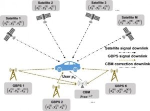
With the intention of performing precise attitude estimation, we have adopted a dual antenna set-up, where two GNSS antennas with a known baseline length are mounted on a vehicle’s rooftop to get an attitude estimation. Furthermore, the absolute position accuracy is augmented using the RTK approach, in which the vehicle is positioned relative to a third receiver, whose position is static and known, used as a virtual reference station (VRS). By knowing the position of the VRS, the vehicle can be positioned absolutely, too. In the positioning algorithm, we strongly rely on carrier-phase positioning which, thanks to its low noise characteristics, may enable decimeter-level positioning. FIGURE 1 shows the typical geometry of our measurement set-up.
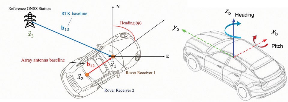
According to Figure 1, the two GNSS antennas on the vehicle’s rooftop span the array antenna baseline b12, which one can resolve for the Euler attitude angles to get the vehicle’s orientation (heading and pitch ).
For each time epoch, we estimate both the RTK position and receiver array attitude. The baseline b13 spanned between one vehicle antenna and the VRS antenna enables us to locate the position of the vehicle relative to the VRS.
MATHEMATICAL MODELS
The realization of GNSS navigation is typically based on a Kalman filter, which is the most popular choice given its optimality and simplicity of implementation. In our study, we developed a position and attitude determination algorithm based on an extended Kalman filter (EKF).
State Transition Model. The state transition or state-space model describes how the states or parameters of the system vary over time based on a specific linear model. In our EKF modeling, the state vector includes five vehicle state parameters and 2 × (Nsat – 1) satellite state parameters: the 3D position of GNSS receiver 1 relative to GNSS receiver 3 (), the pitch angle of the vehicle (), the heading angle of the vehicle (), the DD integer ambiguities of the visible satellites seen by GNSS receiver pair 1-3, and the DD integer ambiguities of the visible satellites seen by receiver pair 2-3. Note that at a given epoch, we can consider different sets of satellites visible for the receiver pairs.
Transition Model for Position- and Attitude-Related State Parameters. In our EKF modeling for the position- and attitude-related state parameters, we suppose that they follow a random walk model, meaning that the speed and the angular rate are a zero-mean Gaussian process.
Transition Model for Satellite-Related State Parameters. The satellite-related parameters are all assumed to be constant over subsequent epochs with very small noise compared to the position- and attitude-related state parameters. The resulting state transition matrix is then given by an identity matrix and different values of process noise variance are added to complete the model.
Measurement Model. The measurement model describes how the individual sensor measurements are related to system states. In general, for every epoch, the measurement vector, which contains all measured values, can be described as a function of the state vector combined with the measurement noise vector, which describes the expected Gaussian noise of every measured value with an associated measurement noise covariance matrix.
In our model, the measurement vector comprises the following measured values: the double-difference (DD) pseudorange (code phase) measurement vector of receivers 1 and 3, the DD pseudorange measurement vector of receivers 2 and 3, the DD carrier-phase measurement vector of receivers 1 and 3, and the DD carrier-phase measurement vector of receivers 2 and 3. The DD measurements are obtained by differencing the single-difference (SD) measurements in the usual way.
In this measurement model, the position of receiver 2 is expressed in terms of the position of receiver 1 and the baseline vector between the two receivers of the array, such that it contains the known array baseline length information and the attitude information that we want to estimate. The individual DD corrected pseudorange and carrier-phase measurements for our short baseline case (less than 3 kilometers) can be modeled using certain approximations such as ignoring the tiny differential atmospheric effects.
To reflect the difference in precision between the pseudorange and carrier-phase measurements, a fixed weighting factor of 1/100 is applied to the pseudorange.
An elevation-angle-dependent measurement noise variance between all satellites is defined to complete the measurement model, defining the measurement covariance matrix.
The relationship between the state and measurement vector is obviously non-linear, thus we need to linearize this measurement function and obtain the measurement (Jacobian) matrix for use in the EKF, as usual. Our algorithm is described in more detail in the proceedings paper on which this article is based (see Further Reading).
Two alternating steps, which are the state prediction step and the state update step, are then conducted to complete the proposed EKF algorithm.
RTK PROCESSING
We first carry out a cycle-slip detection and repair scheme based on multi-epoch measurements. In our work, we use the differential phases over time cycle-slip resolution method. It is based on the observation of the differential phases between two adjacent epochs, which should include the actual jump in the ambiguity if there is one, plus some clock errors and the remaining noise term.
Except for the ambiguity term, all terms contributing to the time-differenced phases change slowly. Any cycle slips will lead to a sudden jump in the time difference of the phases. Based on the past observation of differential phase measurements, a prediction of the current differenced data can be obtained by polynomial extrapolation or interpolation. The residual between the prediction and the observation can then be used as a detector metric, to be compared to the detection threshold to decide whether there are any cycle slips.
After the cycle-slip detection process, a cycle-slip validation and size determination process is conducted to verify the determined sizes of the cycle slips. Cycle slips can be repaired using integer vector estimation similar to ambiguity resolution in the position domain.
After repairing the existing cycle slips, the RTK processing begins. From the previously described EKF process, we first obtain a float estimation of the DD integer ambiguity. The accuracy of the position state estimate is further improved by fixing the DD ambiguities to integer numbers by using the well-known LAMBDA algorithm.
The integer candidates are selected based on the sum of squared errors to get a fixed solution. The candidate with the lowest error norm is chosen once the ratio of the maximum a posteriori error norm between the second-best candidate and the best candidate is bigger than a threshold. It is a pre-defined critical value that the squared norm of ambiguity residuals of the best and second-best candidates should exceed to validate the integer estimation. In our work, we take an empirical fixed value of 3.0.
Once the IAR process is declared successful, a new position is computed using the DD carrier phase measurements corrected by the validated DD integer ambiguities. This final position is a fixed solution. If the IAR process is not declared successful, the final position is kept as the float solution.
SET-UP AND SCENARIOS
In this section, we discuss the verification of our precise position and attitude determination algorithm with real measurements from two low-cost GNSS receivers and one high-end GNSS receiver.
Data Collection. To investigate the feasibility of our proposed precise positioning and attitude determination algorithm, we set up a measurement campaign using four low-cost GNSS patch antennas and took measurements by recording single-frequency (L1) GPS pseudorange and carrier-phase measurements simultaneously at a 1-Hz rate. We put the patch antennas at various distances from each other, ranging from 60 centimeters to about 2.0 meters. In addition, we made the measurements in several different environments including an urban environment, a suburban environment, and an open-sky environment.
FIGURE 2 shows a typical set-up of the GNSS antennas for one of the measurement sessions. According to Figure 1, any two GNSS antennas on the vehicle’s rooftop span the vehicle antenna baseline, which we can resolve for the pitch and heading attitude angles to get the vehicle’s orientation. Additionally, the baseline spanned between one vehicle antenna, and the VRS antenna is able to position the vehicle relative to the latter. If the VRS antenna location is known, the absolute position of the vehicle can be determined.
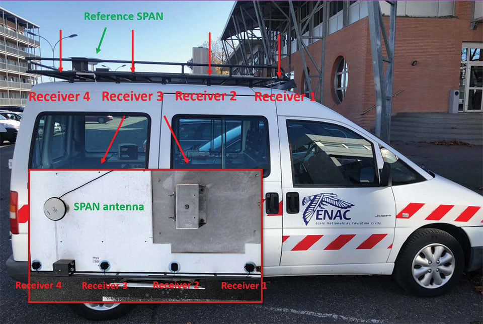
The measurement test was performed with a vehicle on which the following hardware was mounted:
- 4 low-cost GPS receivers with 1 Hz data rate
- 4 L1 patch antennas mounted on the roof of the vehicle along its longitudinal axis
- 1 high-end receiver on the roof of a building as the reference station for RTK processing
- 1 high-end receiver tightly coupled with a tactical-grade inertial measurement unit with an antenna on the vehicle to provide its reference position and attitude.
Data Collection Scenarios. We collected three sets of data in different environments for the analyses described in this article.
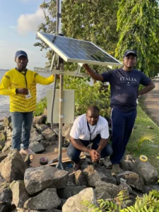
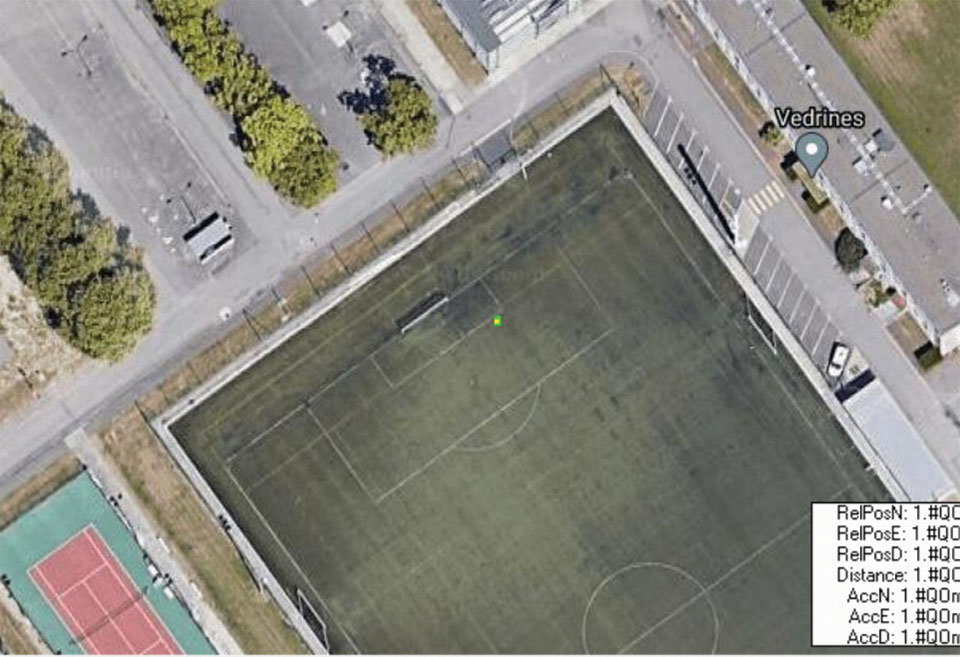
Open-Sky Environment. To get an open sky and stable environment, the first measurement session took place on the football field of the École Nationale de l’Aviation Civile (ENAC) in Toulouse. As shown in FIGURE 3, the two receivers are static and their positions are fixed on the football field with favorable satellite visibility. This scenario was mainly used for validation of the algorithm implementation and to provide a reference for our multi-receiver system performance.
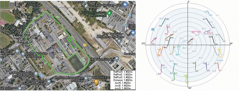
Suburban Environment. The second measurement session took place on the ENAC campus. The true trajectory provided by the high-end equipment and the corresponding satellite visibility during the data collection are shown in FIGURE 4.
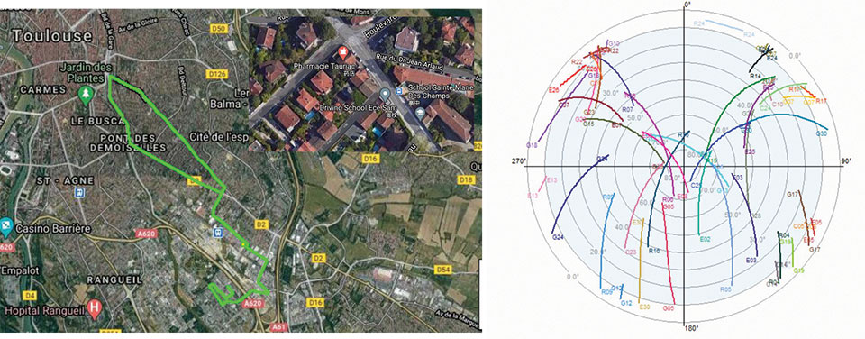
Urban Environment. The third measurement session was performed when the vehicle was driven from ENAC to Toulouse’s city center. The whole trajectory in Google Earth and the corresponding satellite visibility during the data collection are shown in FIGURE 5.
EXPERIMENTAL RESULTS AND DISCUSSION
The datasets we collected allow us to investigate certain aspects of the simulations of our previous work. With our data collection approach, we could vary the distance between the two rover antennas, referred to as the array baseline length elsewhere in this article, as well as the type of environment. In this section, we address the following three points regarding the impact of these two aspects (array baseline and type of environment):
- correlation of measurement error in the measurements collected by an array of receivers
- improvement of cycle-slip detection and repair
- improvement of positioning and attitude accuracy and ambiguity-fixed solution availability.
Experimental Results on the Correlation of Measurement Errors. As the measurements come from signals received by the closely placed antennas, it is safe to consider a certain level of correlation between these measurements. For example, the multipath error from the same satellite may be similar in the measurements recorded by the receivers connected to the two closely-mounted antennas.
By removing the corresponding geometric distance term from the DD pseudorange and carrier-phase observations, the correlation coefficient for the DD pseudorange and carrier-phase observations measured by the different antennas on the same satellite pair can be computed.
We found that the DD phase measurement errors are very correlated, and there is also a medium degree of correlation between the pseudorange measurements. We speculate that this might be due to the characteristic of the GNSS DD measurements.
To make our model closer to the real situation and thereby improve the EKF performance, we updated the observation covariance matrix in the EKF model by replacing the diagonal matrix with one including non-diagonal terms based on the correlation coefficient values we found.
Experimental Results on the Cycle-Slip Detection Performance. We carried out a number of tests on our single-frequency method, which has many limitations. Due to the imperfect detection of cycle slips, a larger ambiguity standard deviation value of 0.1 cycle was chosen to account for possible undetected cycle slips. A slight improvement in positioning results was achieved compared with a smaller value of 0.01.
Typical Positioning and Attitude Determination Performance. We found that the dual-receiver system performs better than the single-receiver situation and provides better solution availability thanks to the doubled observations redundancy.
FIGURE 6 illustrates the 3D RTK positioning estimation error for our multi-receiver method. As one can notice, the algorithm succeeded in outputting a positioning result with an accuracy of about 0.5 meters for the horizontal coordinates, which is acceptable for a harsh environment.
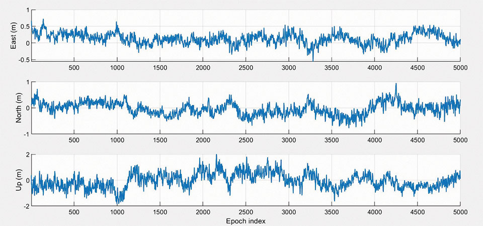
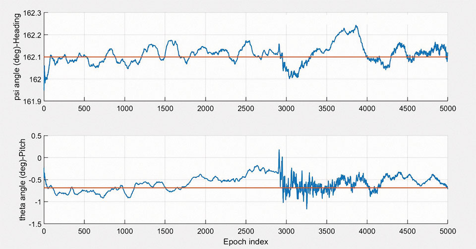
FIGURE 7 shows the estimation of the pitch and heading angles of the vehicle for dataset 1. One can see from the figure that the error between the estimated result and the true value is extremely small (less than 2 degrees), which can provide us with a relatively accurate vehicle posture by using our proposed method.
Experimental Results of the RTK Performance. We found that for our open-sky data, the dual-receiver array system provides better performance than the single-receiver RTK solution, thus demonstrating the usefulness of such an approach.
The results from the analysis of the datasets from the suburban and urban test drives gave us some useful information on the robustness of the multi-receiver RTK system in harsh environments.
As previously mentioned, the suburban data was collected when the vehicle was driven on the ENAC campus. The reference trajectory was provided with centimeter-level accuracy. The maximum standard deviation values, up to 10 centimeters, occur at around the 500-epoch mark, which corresponds to the zone having a minimum number of visible satellites. Generally, however, the environment is quite favorable with at least eight satellites in view for most of the time.
We have compared the results from the single-receiver system and our multi-receiver system in terms of the ambiguity fix success rate, the horizontal positioning (east and north directions), error statistics (mean, standard deviation, and 95% error bound), and array attitude error statistics for all three data collections. As an example, TABLE 1 gives the performance comparison between our dual-receiver system and the single-receiver system in the suburban environment and for different array baseline lengths. A better accuracy result is obtained in the dual-receiver situation.
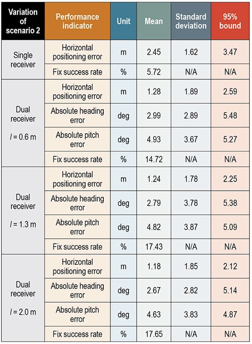
Moreover, there is no huge difference in the accuracy of the positioning results between the different dual-receiver variations. However, as expected, the attitude accuracy does improve slightly as the array baseline length increases.
The high-end GNSS receiver with IMU provided a decimeter-level trajectory accuracy in the urban scenario. The number of visible satellites was much lower than for the other two environments. A clear uncertainty increase in the position solution was observed in the reference result during the trajectory section where the number of satellites was fewer than six. We also obtained satisfactory results from our urban scenario test. We can conclude that the use of an array of receivers with known geometry to improve RTK performance is feasible and effective.
CONCLUSION
In this article, we have presented a method that includes an array of receivers with known geometry to enable vehicle attitude determination and enhanced RTK performance in different environments. Taking advantage of the attitude information and the known geometry of the array of receivers, we are able to improve some of the steps of precise position computation.
We demonstrated through real data processing results that our multi-receiver RTK system is more robust to degraded satellite geometry, in terms of ambiguity fixing rate, and obtains a better position accuracy under the same conditions when compared with the single-receiver system.
ACKNOWLEDGMENTS
The research described in this article was supported by the China Scholarship Council. The article is based on the paper “Attitude Determination and RTK Performances Amelioration Using Multiple Low-Cost Receivers with Known Geometry” presented at the virtual 2021 International Technical Meeting of The Institute of Navigation, Jan. 25–28, 2021.
MANUFACTURERS
Our equipment included four U-blox (www.ublox.com) F9P GNSS receivers fed by U-blox ANN-MB series multi-band patch antennas, a Hexagon | NovAtel (www.novatel.com) ProPak6 SPAN GNSS receiver with integrated tactical-grade IMU and a NovAtel Pinwheel GPS-702-GG antenna, and a Septentrio (www.septentrio.com) AsteRx-U GNSS receiver with a Hexagon | Leica (leica-geosystems.com) AR20 choke ring antenna as the base station for RTK processing.
XIAO HU is a Ph.D. student in the Signal Processing and Navigation (SIGNAV) research group of the TELECOM laboratory at École Nationale de l’Aviation Civile (ENAC) in Toulouse, France.
PAUL THEVENON is an assistant professor at ENAC.
CHRISTOPHE MACABIAU is the head of ENAC’s TELECOM team, which includes research groups in signal processing and navigation, electromagnetics, and data communication networks.
FURTHER READING
(Coming soon)