No audio available for this content.
Enter the BinoNav
An electronic pelorus is poised to become a useful tool in any mariner’s toolbox of resilient PNT systems. Learn how it works, and the benefits it brings to position fixing at sea.

POP QUIZ: What do a character from Greek mythology, a point on the coast of Sicily, the pilot of Hannibal’s ship, a fizzy wine from New Zealand, and a navigation instrument have in common?
They are all called Pelorus or pelorus in the case of the instrument as it’s not a proper noun (grammar lesson over). And while a discussion of each of the uses of the word could be quite educational, this month’s column, perhaps predictably, will be about the pelorus or rather a modernized version of it.
If you are a landlubber, like me, you may not have heard of the pelorus. Yet, in one form or another it has been around for hundreds of years although not always going by that name. In appearance and use, it resembles a compass with sighting vanes.
But it has no magnetic components of any sort. And while a compass is used to get a magnetic bearing of a charted feature such as a tower or lighthouse or the magnetic heading of a vessel, a pelorus is used to measure a relative bearing between a feature and a reference direction such as the heading of the vessel, commonly called the ship’s head.
If a line is drawn on a chart through the sighted feature at an angle equal to the measured bearing, the vessel must be somewhere along this so-called line of position. If a second bearing on another feature significantly displaced from the first is measured in quick succession, a second line of position can be drawn on the chart, crossing the first.
The intersection point gives the (two-dimensional or horizontal) location, or position fix, of the vessel. Since the measured bearings will have some error, generally at least three lines of position are established with their intersections forming a small triangle, sometimes called a “cocked hat.” The location of the vessel is either inside the triangle or nearby depending on the similarity of the bearing errors.
Position fixes can also be obtained from instruments that measure ranges. In this case, the lines of position are circles for terrestrial systems providing two-dimensional fixes or spheres of position in the case of three-dimensional fixes obtained from GNSS measurements.
But let’s get back to the pelorus. Most vessels of a certain size are equipped with a pelorus. Frequent use of the pelorus helps to maintain situational awareness and being a completely passive device, it is not dependent on receiving an electronic signal of any kind. Only an acceptable level of visibility is required. And it can provide a manual check on any automated ship’s systems such as a GNSS receiver.
However, determining position fixes using a pelorus and a paper chart is laborious and time consuming and it is cumbersome to manually add lines of position to an electronic chart. What is needed is an electronic pelorus, which measures bearings electronically and automatically generates a line of position on an electronic chart.
The General Lighthouse Authorities of the United Kingdom and Ireland, the agencies responsible for aids to navigation in the U.K. and Ireland, have developed such an instrument. Dubbed the BinoNav, it is poised to become a useful tool in any mariner’s toolbox of resilient PNT systems and in this month’s column, we learn about its genesis, how it works, and the benefits it brings to position fixing at sea.
The overreliance on GNSS is well known and widely publicized. While GNSS is generally available, concerns remain on how maritime operations, and safe navigation in particular, are affected should GNSS not be usable, or become denied for any reason.
The General Lighthouse Authorities of the United Kingdom and Ireland (GLA) have been working on resilient positioning, navigation and timing (PNT) for many years. This work has included a comprehensive review of different potential solutions and their availability. One option proposed is the development of a ship-based positioning system that makes use of a modernized pelorus to work with a modern bridge.
Pelorus systems work by providing bearings from fixed positions, normally on the vessel bridge wings, to specific targets visible to the mariner and identified on the navigation chart. By taking several bearings in quick succession, intersecting lines can be drawn on the navigation chart, providing a position estimation. Clearly, there are limitations to this approach — these are explored within this article, but can be summarized as:
- Automation. The time taken to measure the bearings can limit the achieved accuracy.
- Visibility. Performance is limited by the mariner’s ability to see unique targets.
- Paperless bridges. Many vessel bridges are moving away from paper, limiting the mariner’s ability to take bearings and plot them.
- e-Navigation. More bridge systems require electronic values of latitude and longitude.
In an attempt to resolve most of these limitations, the GLA has been working on the development of an enhanced pelorus, or ePelorus, with its name registered to the Research and Radionavigation Directorate (R&RNAV) as BinoNav.
Prototype BinoNav systems have been developed and installed on all GLA vessels for trial. They enable the navigator to take visual bearings to known targets, from anywhere on the bridge using a handheld device — they are no longer confined to the bridge wings and targeting port or starboard objects.
Measured bearings are automatically registered and drawn on an electronic chart. Multiple bearings can then be made with ease, each of which is displayed on the chart and the intersecting “cocked-hat” position (to be discussed later), calculated automatically. This information can then be used to feed other bridge systems and confirm the vessel’s position.
In this article, I will provide a comprehensive overview of the BinoNav system, provide the results of initial trials and explain the planned development of the proposed resilient PNT solution.
e-NAVIGATION
Much has been written about e-Navigation elsewhere, but briefly, it is the International Maritime Organization’s (IMO’s) concept for the future of navigation, instigated by the U.K. Department for Transport in 2004. It will lead to the integration of systems and data — for the exchange of relevant geolocated information — faster and more cost effectively, and it will do this in the context of larger, faster vessels operating in ever more constricting shipping lanes and increasing offshore obstacles such as renewable energy infrastructure as well as the legacy of non-renewable energy infrastructure.
e-Navigation is designed to enhance safety of life for the mariner, improve protection of the environment, and increase energy efficiency in terms of shorter routing for fuel-efficient shipping. Moreover, it will allow more effective use of resources and integration across transport modes, including the more effective provision of integrated port operations.
Since its inception in 2004, development and delivery of e-Navigation services has been slow. Even now, some 14 years later, only a few prototype projects have delivered anything like what was anticipated in the original e-Navigation vision. This sluggishness has been caused by minimal leadership and drive from the IMO.
Despite this, some initiatives have been successfully delivered on a local or regional basis. These initiatives have come largely through projects such as Accessibility for Shipping, Efficiency Advantages and Sustainability (ACCSEAS), Efficient Safe and Sustainable Traffic at Sea (EfficienSea) 1 & 2, Motorways and Electronic Navigation by Intelligence at Sea (MonaLisa) 1 & 2, and Sea Traffic Management (a MonaLisa project), all of which have been supported by funding from the European Union.
Resiliency in PNT has been identified by the IMO as a lead area in the delivery of e-Navigation, and all these projects have used resilient PNT as the basis of what they have delivered.
REQUIREMENT FOR RESILIENT PNT
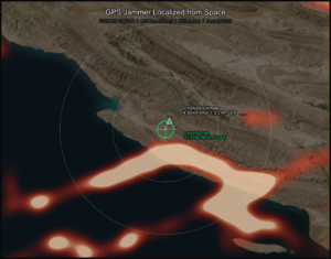
It is now well recognized that all GNSS are vulnerable to interference, whether these interferers are from natural causes such as space weather or from synthetic sources such as jamming or spoofing devices. GNSS receiving units and satellite failures also occur. There are many examples of each of these problems affecting GNSS worldwide.
Resilient PNT information is needed to ensure continuity of maritime operations and safe navigation — especially for e-Navigation, management of sea traffic, and autonomous vessels.
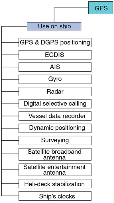
GPS jamming trials were conducted by GLA’s R&RNAV in 1994, 2008, 2009 and 2012. These trials showed the real-time vulnerability of maritime systems to jamming. They identified that many ships’ systems were affected by GPS jamming. However, some systems we did not expect to be affected actually were (see Figure 1). Devices such as the helicopter-deck stabilization system and the ship’s gyrocompass are good examples.
GLA Work on Resilient PNT. GLA, through R&RNAV, has conducted a program of work that has looked at the issues of GNSS vulnerability and what they can do about it through a series of studies. These have looked at a number of systems such as
- enhanced Loran, absolute radar positioning (two different methods)
- ranging mode or R-mode, which is the use of ranging signals from existing marine infrastructure (two different methods)
- signals of opportunity (many methods)
- hybrid systems
- dead reckoning
- inertial
- other on-board systems.
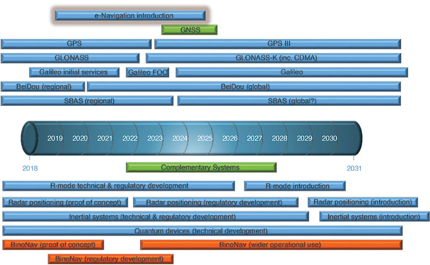
The timeline for the introduction of some of these systems into operational use, as well as current and new GNSS, can be seen in Figure 2. This article deals with equipment that falls into the “other on-board systems” category.
A DRIVER FOR OPTICAL NAVIGATION SYSTEMS
The need for new optical navigation systems has been driven by a number of marine incidents, one of which I will discuss in detail.
MV Tricolor Incident. On Dec. 14, 2002, in early morning thick fog, on its way from Zeebrugge to Southampton, the MV Tricolor, with a load of almost 3,000 BMW, Volvo and Saab cars, collided with a Bahamian-flagged container ship named Kariba, about 20 miles north of the French coast in the Dover Strait Traffic Separation Scheme.
Albeit damaged above the water line, the Kariba could continue, while the MV Tricolor remained wedged on her side in 30 meters of water in a busy area of navigation. No lives were lost and the crew were rescued by the Kariba and a tugboat. Nevertheless, approximately 2,862 cars and 77 units of cargo, consisting mainly of tractors and crane parts, could not be salvaged.
The shipping lane, being the busiest in the world, was marked by buoys and guarded by the French police vessel Glaive and HMS Anglesey, thereby warning other vessels of the MV Tricolor’s presence. Despite the marking and patrolling, only two days later a cargo ship, Nicola, followed by another vessel, Vicky (carrying 70,000 tonnes of highly flammable gas oil) collided with the wreck of the Tricolor, after failing to heed several French naval warnings. In between the two further collisions, more buoyage and patrol vessels were deployed. On Jan. 22, a third accident happened when a salvage tug knocked a safety valve off the Tricolor, resulting in a massive oil spill.
Besides the heavy economic losses, including the estimated operation cost of around £25M (roughly $40M), the incident caused massive marine pollution and environmental contamination by spilling large quantities of oil. The Royal Society for the Protection of Birds estimated more than 1,000 birds were found dead or damaged by oil spilled from Tricolor.
Why Did It Happen? The incident was blamed on declining professional standards among seafarers, which was leading to scores of near misses in the area every day. Indeed, Andrew Linnington of the National Union of Marine Aviation and Shipping Transport Officers is quoted as saying that ship owners had been cutting costs by reducing use of deep-sea pilots to guide vessels through the world’s most crowded shipping lanes. Ships were increasingly crewed by one trained officer and a few poorly paid sailors from parts of the developing world.
“We know of at least four cases in the past year of ships going the wrong way in shipping lanes against the flow of traffic,” Linnington said. “Complaints are made to the states where the ships are registered, but they are often small countries used as flags of convenience and don’t have the resources to take action.”
It is clear from the incident and the ensuing investigation that navigators were not looking out the window, despite various radio navigation warnings and other methods, not the least of which was deploying wreck-marking buoys and virtual aids to navigation.
A very good way of mitigating the failure of any navigation system is by using reversionary methods of navigation, like looking out the window! This was a big driver in the GLA development of the BinoNav.
WHAT IS BINONAV?
BinoNav is an electronic pelorus. A pelorus is a device that is completely independent of any other system or electronic position fixing system (EPFS), and this is important for providing resiliency.
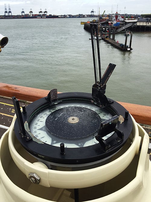
Pelorus. A standard pelorus (see Figure 3) is used to take relative (to the vessel’s head) bearings to charted objects in the vicinity. The navigator then draws a line on the relevant navigation chart through the charted object. It is clear now that the vessel lies somewhere on this “line of position” from the charted object. This process is then repeated several times using different charted objects, with a minimum of three iterations.
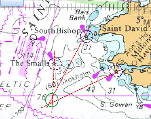
This process then creates a “cocked hat” (a triangle in the case of three lines of position) generated from the intersection of the lines. Accounting for systematic errors, the vessel should lie somewhere within this cocked hat (see Figure 4 for an example).
This process is laborious and time consuming, but it does have the advantage of getting the navigator to look at real features outside the vessel — not just a red line on an electronic chart that they follow without question.
What about Electronic Chart Display? Electronic Chart Display and Information Systems (ECDISs) are excellent, when used correctly, and have driven innovation in the shipping industry. However, they do have disadvantages: If you are using a pelorus, you cannot very easily draw on a screen. You can generate an electronic bearing line (EBL) on an ECDIS, but it is a very long, convoluted way of providing a position not derived from an EPFS, such as a GNSS fix.
Any system that needs to generate an EBL on an ECDIS needs to do it electronically. Moreover, it needs to do this without having to rely on GNSS for position or time to avoid the issues of GNSS vulnerability: it should be completely independent. It should also be able to carry out optical to electronic integration to ensure that the mariner is looking out the window. Another GLA requirement was that it should be relatively low cost to make and distribute to enable take up across all users. So the idea of BinoNav was born. BinoNav fulfills all these criteria easily, intuitively and quickly, updating the electronic position of the vessel. Furthermore, with its wireless connection, bearings can be taken anywhere on the bridge of a vessel.
BINONAV FEATURES
In this section, I will describe the BinoNav and how it is used.

Easy to Use. BinoNav comprises two parts: the “Bino” unit, which is a modified pair of binoculars, and a “base” unit that performs the communication link between the Bino unit and the electronic chart. Pick up the Bino unit from the base unit (see Figure 5 for overall configuration of the BinoNav).
Line up the graticule inside the Bino unit with a charted feature of use, press either of the buttons to automatically generate a line on the displayed electronic chart, which is relative to the ship’s head. As with a standard pelorus, one needs at least another two of these EBLs to generate a cocked-hat position on the electronic chart. Using either the touch screen or the mouse, “hover” over the cocked hat to generate a triangle. Now, right click to drop a marker at the center of the cocked-hat position and delete all lines. Once the vessel has moved (and dictated by the operating environment at the time), this process can be repeated. When two or more of the markers have been dropped, a line is drawn between the marks, thereby showing a track on the chart.
Features. From the use of the BinoNav unit as described above, a track is produced on an electronic chart that is not derived from an EPFS. This is important as it shows the integration of visual navigation into e-Navigation, something which e-Navigation has tried to do from the very beginning, as described by Brian Wadsworth in his earliest vision of e-Navigation (see Further Reading).
Another feature of BinoNav is “radar mode” for charted feature recognition. This feature draws a continuously moving line on the display that points at the position relative to the ship’s head. This is useful for the recognition of charted features when in unfamiliar territory.
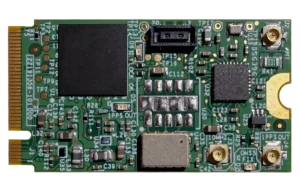
The BinoNav is very easy to install, with only a connection for power and a connection for a suitable National Marine Electronics Association (NMEA) protocol data feed for heading. Many of its electronic components are available off the shelf and are widely available commercially with bespoke printed circuit boards. Some modification to the binocular unit has been necessary, with the addition of a bespoke unit, which links to the base unit for both orientation measurement and power when the unit is docked. The binoculars are readily available for around $500. The gyros incorporated in both the base unit and the binocular unit are high-grade microelectromechanical systems (MEMS) devices giving an angular resolution of 0.25-0.5 degrees, similar to that of a standard pelorus.
Currently, the BinoNav is 3D-printed, which allows for the quick production of one-off units. However, this approach is clearly not a suitable solution for long production runs and would require a different method of production.

Something for the Future. R&RNAV has received a lot of interest in the BinoNav not only from our own mariners, but also from a variety of influencers in the maritime world. We have had a great deal of positive feedback on potential improvements and additional features that we plan to develop.
We will also seek to gain approvals through IMO and the International Electrotechnical Commission to integrate BinoNav with ECDIS, so there will be no need for separate displays (unless being used on non-SOLAS vessels; that is, ones to which the International Convention for the Safety of Life at Sea does not apply.)
CURRENT GLA INSTALLATIONS
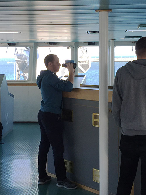
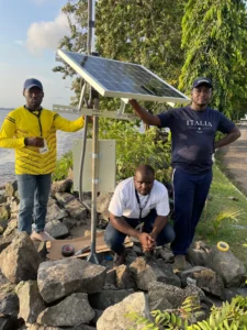
The BinoNav has been installed on all six GLA vessels: ILV (Irish Lights Vessel) Granuaile, NVL (Northern Lighthouse Vessel) Pharos, NVL Pole Star, THV (Trinity House Vessel) Alert, THV Galatea and THV Patricia. The installation on Alert is shown in Figure 6 and BinoNav use on Granuaile is shown in Figure 7.
CONCLUSIONS
The key points made in this article can be summarized as follows:
- e-Navigation is based on the premise of electronic navigation from “berth to berth.”
- Many accidents happen because crews do not look out the window.
- There is a need for electronic positioning from non-GNSS sources.
- The BinoNav integrates visual navigation and electronic navigation through an ECDIS.
- The BinoNav provides an independent verification of position with or without EPFS.
INTELLECTUAL PROPERTY
BinoNav is a registered trade mark and carries unregistered design rights. BinoNav has patents pending.
ACKNOWLEDGMENTS
The author thanks the masters, officers and crews of all the GLA vessels for their help and for the benefit of their experience throughout the whole process of the BinoNav development. Special thanks go to those who helped during the various development trials on ILV Granuaile and THV Alert prior to the mainstream installations.
This article is based on the paper “BinoNav® – A New Positioning System for Maritime” presented at ION GNSS+ 2018, the 31st International Technical Meeting of the Satellite Division of The Institute of Navigation, Miami, Florida, Sept. 24–28, 2018.
MARTIN BRANSBY is the head of the Research and Radionavigation Directorate at the General Lighthouse Authorities of the UK and Ireland, stationed in Harwich, Essex. He is responsible for the delivery of its program portfolio in research and development in technically diverse areas such as resilient PNT, e-Navigation, GNSS, Automatic Identification System (AIS) and visual signaling. He is a fellow of the Royal Institute of Navigation, and holds memberships in the Institute of Engineering and Technology and The Institute of Navigation. He is also a member of the International Association of Marine Aids to Navigation and Lighthouse Authorities’ AtoN (Aid to Navigation) Requirements and Management Committee.
FURTHER READING
- Author’s Conference Paper
“BinoNav® – A New Positioning System for Maritime” by M. Bransby in Proceedings of ION GNSS+ 2018, the 31st International Technical Meeting of the Satellite Division of The Institute of Navigation, Miami, Florida, Sept. 24–28, 2018, pp. 1728–1735.
- The Sinking of the Tricolor
“MV Tricolor.” Wikipedia article: https://en.wikipedia.org/wiki/MV_Tricolor
“Tricolor/Kariba.” Report by Cedre: Centre of Documentation, Research and Experimentation on Accidental Water Pollution, Aug. 31, 2004.
“The Tricolor Incident: From Collision to Environmental Disaster” by F. Kerckhof, P. Roose, and J. Haelters in Atlantic Seabirds, Vol. 6, No. 3, 2004, pp. 85–94.
“Cargo Ship Hits Sunken Car Carrier” by O. Bowcott and A. Clark in The Guardian, Dec. 17, 2002.
- eNavigation
“Marine eNavigation: An Orientation Paper” by B. Wadsworth, document WEND9-INF4, presented to the 9th meeting of the International Hydrographic Organization World-wide Electronic Navigational Chart Database (WEND) Committee, Monaco, April 7–8, 2005.
- GPS Jamming and Its Consequences
Satellite-derived Time and Position: A Study of Critical Dependencies, edited by S. Battersby, U.K. Government Office for Science, London, U.K., 2018.
The Economic Impact on the UK of a Disruption to GNSS by G. Sadlier, R. Flytkjær, F. Sabri and D. Herr, London Economics, June 2017.
“Know Your Enemy: Signal Characteristics of Civil GPS Jammers” by R.H. Mitch, R.C. Dougherty, M.L. Psiaki, S.P. Powell, B.W. O’Hanlon, J.A. Bhatti and T.E. Humphreys in GPS World, Vol. 23, No. 1, January 2012, pp. 64–72.
“The Impact of GPS Jamming on the Safety of Navigation” by S. Basker, A. Grant, P. Williams and N. Ward, presented at the 48th meeting of the Civil GPS Service Interface Committee, Savannah, Georgia, Sept. 15–16, 2008.