No audio available for this content.
By Peter Steigenberger, Steffen Thoelert, Oliver Montenbruck and Richard B. Langley
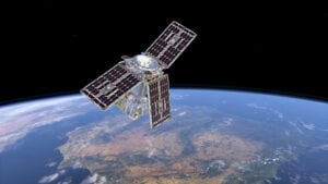
The first GPS III satellite, “Vespucci,” was launched in December 2018, started signal transmission in January 2020, and was set healthy later that month. The second GPS III satellite, nicknamed “Magellan,” was launched on Aug. 22, 2019, on a Delta IV rocket from Cape Canaveral, Florida.
Magellan, also identified by its space vehicle number (SVN) 75 (here referred to as GPS-75), started signal transmission with standard pseudorandom noise code (PRN) number 18 (here referred to as G18) on March 13. The L1 C/A, L1 P(Y), and L2 P(Y) signals were activated at 17:16:30 GPS Time (GPST), while the L1C, L2C and L5 signals followed less than two hours after Vespucci’s launch at 18:59:30 GPST. Transmission of navigation messages started at 19:00:00 GPST with GPS-75 (G18) marked as unhealthy.
PRN G18 was previously used by the 27-year-old Block IIA satellite GPS-34 that had been already removed from the active GPS constellation on Oct. 7, 2019, but continued signal transmission until March 9, 2020. GPS-75 is already being tracked by a large number of tracking stations of the International GNSS Service (IGS). Based on the data collected by these stations, the Center for Orbit Determination in Europe (CODE), headquartered in Bern, Switzerland, has been providing precise orbit and clock products for this satellite since March 14.
A comparison we performed with the CODE precise orbit products revealed initial broadcast ephemeris errors of up to 100 meters (3D) and an orbit-related signal-in-space range error (SISRE) of about 13 meters. Within four days, a SISRE (orbit component) of 24 centimeters was achieved, which closely matches the performance of the rest of the GPS constellation.
Figure 1 shows the spectral flux density of GPS-75 in the L1, L2 and L5 frequency bands obtained with the 30-meter high-gain antenna of the German Aerospace Center (DLR) located in Weilheim, Germany. The civil L1 C/A, L1C and L2C signals can be identified as sharp peaks in the center of the respective frequency bands.
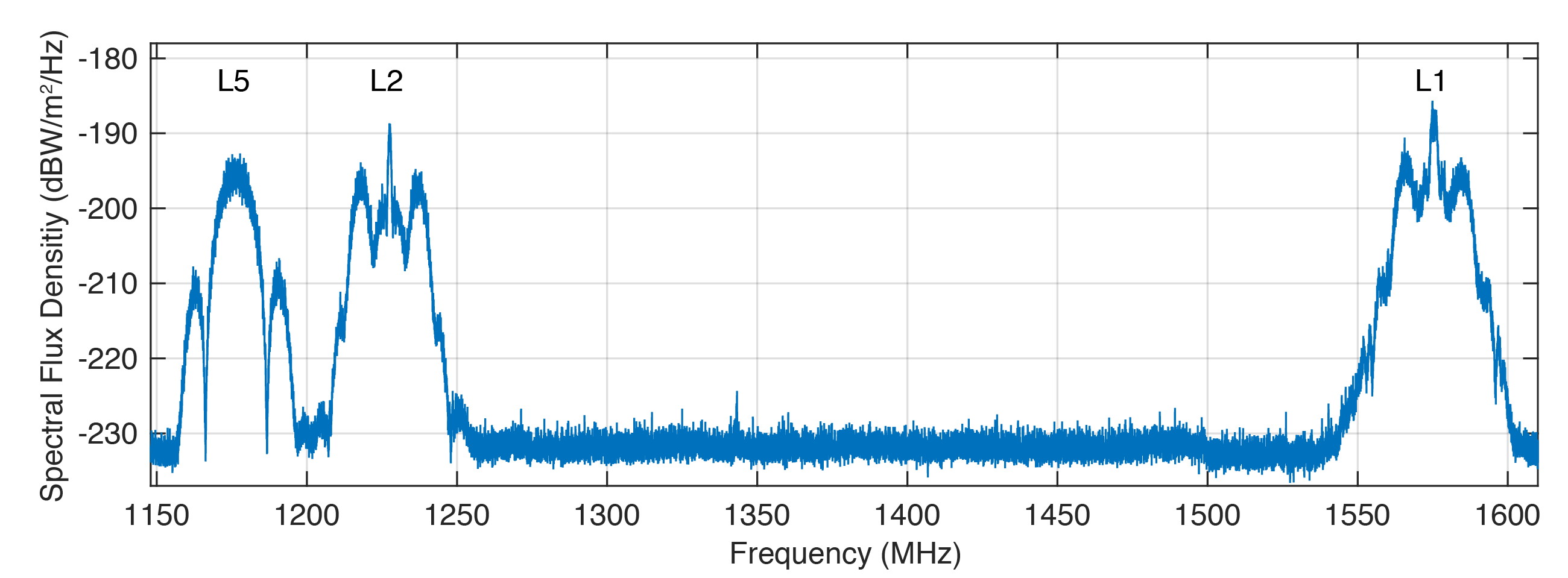
The prominent side lobes in the L1 and L2 bands are associated with the military M-code. The wide main lobe of the L5 signal with two smaller and sharper side lobes is caused by the superposition of two in-phase and quadrature signals with a 10-MHz binary phase-shift keying (BPSK) modulation. We found that all signals are in good shape and have a quality similar to that of the first GPS III satellite.
On March 16, 2020, we detected a significant change in the carrier-to-noise-density ratio of the L1 and L2 P(Y)-code signals. Figure 2 illustrates these changes for the IGS station located in Patumwan, Thailand (CUSV00THA). The L1 and L2 P-code signals are usually encrypted with the W-code to prevent spoofing (the generation of fake signals by adverse parties). The resulting encrypted signals are denoted by P(Y). Geodetic GNSS receivers are capable of tracking the P(Y) signals with a semi-codeless approach.

As a result, C/N0 of L1 P(Y) and L2 P(Y) are virtually identical and significantly smaller than the C/N0 of the unencrypted signals due to losses of the semi-codeless tracking technique. This can be seen in the blue-colored plot of Figure 2, where the C/N0 values of L1 P(Y) and L2 P(Y) are identical and smaller by 4.5–16 dB compared to L1 C/A depending on the elevation angle of the satellite.
However, between 20:22 and 21:18 GPST, an increase of the P-code C/N0 values was observed. The values changed by 4.5 and 12.5 dB for L1 and L2, respectively. This change is an indicator that unencrypted P-code signals were transmitted, rather than encrypted ones. This assumption can be verified by the “Anti-Spoof Flag” given as the 19th bit of the handover word (HOW) of the GPS LNAV navigation message.
Indeed, decoding of the raw navigation data from the IGS station CHOF00JPN in Chofu, Japan, showed that the Anti-Spoof Flag indicated a deactivation of anti-spoofing between 20:22:00 and 21:17:48 GPST and verified our assumption that unencrypted P-code signals were transmitted during that time period.
It has to be noted that only Javad receivers within the global multi-GNSS network of the IGS show this increase in C/N0. Other receiver types report continuous C/N0 values for the P-code signals, indicating that a semi-codeless tracking technique was continuously applied irrespective of the Anti-Spoof Flag.
Figure 3 shows the two GPS III satellites’ Allan deviation, which measures the clock stability achieved in orbit; that is, the average frequency error over different time scales. In addition, the Block IIF satellite GPS-63 is shown, which is in the same orbital plane as GPS-75.
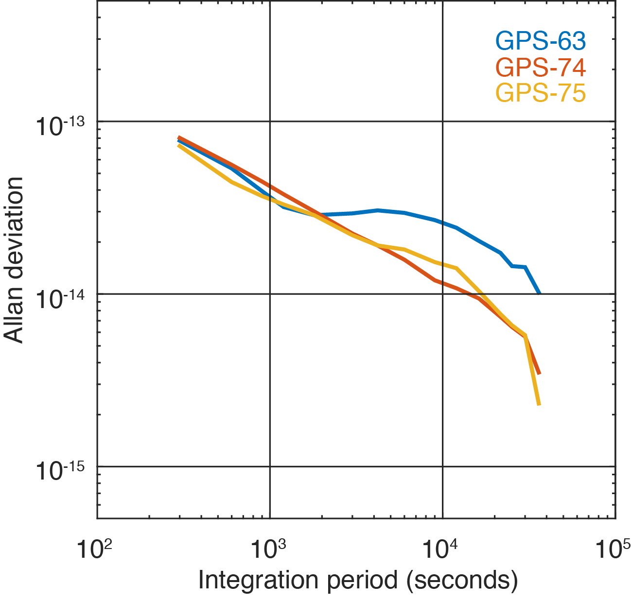
For integration times up to 2,000 seconds, the clock stability of GPS-75 is slightly better compared to the first GPS III satellite, GPS-74, but the situation is opposite for integration times larger than 5,000 seconds. The latter finding might be caused by the fact that GPS-75, unhealthy at the time, was tracked by a smaller number of stations compared to the healthy GPS-74.
As a consequence, the observed Allan deviation may partly be contaminated by orbit determination errors. In any case, both GPS III satellites clearly outperform the Block IIF satellite GPS-63 that suffers from thermal line bias variations visible as an increased Allan deviation starting at an integration time of about 2,000 seconds.
The activation of the second GPS III satellite transmitting the new civil L1C signal enables the estimation of differential code biases (DCBs) between, for example, the L1 C/A signal (Receiver Independent Exchange [RINEX] format observation code C1C) and different tracking modes of the L1C signal. Septentrio receivers track only the pilot component of the L1C signal (C1L), whereas Javad and Trimble receivers perform a combined data+pilot tracking (C1X).
DCBs are estimated from pseudorange (code) observations of a global tracking network and are corrected for ionospheric delays obtained from global ionosphere maps. The DCB estimates shown in Table 1 are based on eight days of data from 10 Javad, 21 Septentrio and 3 Trimble receivers.

As we have applied a zero-sum condition for the estimation of satellite DCBs of just two satellites, the values of GPS-74 and GPS-75 obtained from the same type of L1C observables differ only by the sign. The DCBs estimated from different L1C observables, namely C1L and C1X, differ by 56 picoseconds, corresponding to a range difference of 1.7 centimeters. The receiver DCBs are quite homogeneous for receivers from each manufacturer but differ by up to 6 nanoseconds between various manufacturers.
On April 1, 2020, GPS-75 was set healthy and joined the constellation of operational GPS satellites. The third GPS III satellite, named “Columbus,” was shipped to the Cape Canaveral launch site in February 2020. Its launch is expected no earlier than June 30, 2020, and at least two GPS III launches per year are planned for the near future.
Equipment. Measurements reported in this article were collected with JAVAD GNSS TRE_G3TH and TRE_3, Septentrio PolaRx5 and Trimble Alloy multi-GNSS, multi-frequency receivers. The spectral overview was captured with a Rohde & Schwarz EM100 digital compact receiver.
PETER STEIGENBERGER and OLIVER MONTENBRUCK are scientists at the German Space Operations Center of the German Aerospace Center (DLR). STEFFEN THOELERT is an electrical engineer at DLR’s Institute of Communications and Navigation. RICHARD B. LANGLEY is a professor at the University of New Brunswick and editor of the “Innovation” column for GPS World magazine.
Further Reading
“Optimum Semicodeless Carrier-Phase Tracking of L2” by K.T. Woo in Navigation, Vol. 47, No. 2, 2000, pp. 82-99, doi: 10.1002/j.2161-4296.2000.tb00204.x.
Interface Specification IS-GPS-200K: NAVSTAR GPS Space Segment/User Segment Interfaces by Global Positioning Systems Directorate Systems Engineering & Integration, Los Angeles Air Force Base, El Segundo, California, March 4, 2019. Available online: https://www.gps.gov/technical/icwg/IS-GPS-200K.pdf
“Apparent Clock Variations of the Block IIF-1 (SVN62) GPS Satellite“ by O. Montenbruck, U. Hugentobler, E. Dach, P. Steigenberger and A. Hauschild in GPS Solutions, Vol. 16, No.3, 2012, pp. 303-313, doi: 10.1007/s10291-011-0232-x.
“Differential Code Bias Estimation Using Multi-GNSS Observations and Global Ionosphere Maps” by O. Montenbruck, A. Hauschild and P. Steigenberger in Navigation, 2014, Vol. 61, No. 3, 2014, pp. 191-201, doi: 10.1002/navi.64