No audio available for this content.
Less than three weeks after its launch, the first GPS III satellite, SVN74, started transmitting navigation signals. SVN74 uses the pseudorandom noise (PRN) code number G04 previously used by the almost 25-year-old Block IIA satellite SVN36. The L1 C/A, L1 P(Y), and L2 P(Y) signals of SVN74 have been tracked since Jan. 9 at 00:01 UTC. Activation of the L2C and L5 signals followed on the same day at 19:43 UTC. Transmission of the legacy navigation message (LNAV) started Jan. 9, but the satellite is still marked unhealthy for ongoing on-orbit check out and testing.
Also, SVN74 is the first GPS satellite to transmit a new civil signal on the L1 frequency (1575.42 MHz), namely L1C, which was initially activated on the same day as the other SVN74 signals. Incidentally, the L1C signal was already being transmitted by the four satellites of the Japanese Quasi-Zenith Satellite System (QZSS).
Compared to the L1 C/A PRN codes, the L1C codes are 10 times longer (10,230 chips), reducing interference when multiple satellites are tracked by a receiver on the same frequency. Like L2C and L5, the L1C signal consists of a dataless pilot component and the data component with navigation data. Dataless signals enable more robust tracking under difficult conditions. For the L1C signal, 75 percent of its power is put into the pilot component.
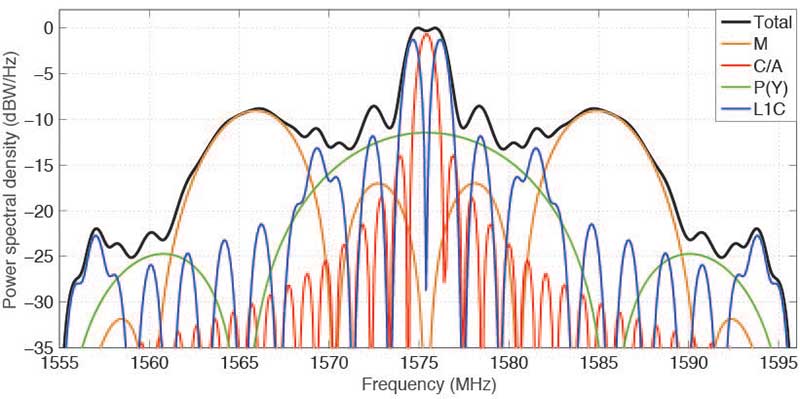
The theoretical spectra of the four signals transmitted on L1 by SVN74, namely the civil C/A-code and L1C, as well as the military P(Y)-code and M-code, are shown in FIGURE 1 along with the the total (summed) spectrum.
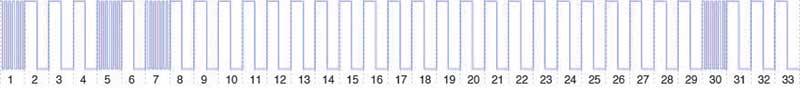
BOC. To achieve compatibility with the L1 C/A-code signal at the same center frequency, a binary offset carrier (BOC) modulation is used for spectral separation of L1C from L1 C/A. A BOC(n,m) signal is characterized by the fundamental frequency of the square wave subcarrier expressed in multiples n of the basic frequency of 1.023 MHz and the chipping rate expressed in multiples m of 1.023 megachips per second. A BOC(1,1) modulation is used for the L1C data component. For the pilot component, a time-multiplexed binary offset carrier (TMBOC) is used. The spreading waveform, with a length of 33 symbols, consists of four BOC(6,1) and 29 BOC(1,1) symbols as illustrated in FIGURE 2 resulting in a TMBOC(6,1,4/33) signal. The additional BOC(6,1) component allows for improved multipath mitigation.
Similar to GPS L1C, the European Galileo and the Chinese BeiDou-3 systems employ multiplexed BOC signals with BOC(1,1) and BOC(6,1) components in the L1 frequency band. A composite BOC (CBOC) modulation has been adopted for the Galileo E1 open service signal, which uses a weighted sum of the BOC(1,1) and BOC(6,1) components in both the data and the pilot channels. For the BeiDou B1C signal, BOC(1,1) is used for the data channel, while a quadrature multiplexed BOC modulation, QMBOC(6,1,4/33), with BOC(1,1) and BOC(6,1) subcarriers in phase quadrature, is used for the pilot channel.
Interoperability. The new civil L1 signals of GPS, Galileo and BeiDou show a high level of commonality and are specifically designed for full interoperability. This means that receivers can easily track signals of all three constellations and use the measurements to compute a combined multi-GNSS position solution. Aside from the similar signal modulations, the interoperability is further supported by the transmission of inter-system timing biases (such as the GPS-Galileo Time Offset) in the navigation messages.
The binary phase shift keying (BPSK) modulation of the C/A-code with a 1.023-MHz chipping rate introduces a main lobe at the center frequency of 1575.42 MHz and numerous side lobes with decreasing amplitude. The 10.23-MHz BPSK signal of the P(Y)-code is visible in Figure 1 as a broad peak at the center frequency and first side lobes at about 1560 and 1590 MHz. The M-code is characterized by its main lobes ±10.23 MHz from the center frequency due to its BOC(10,5) modulation. Finally, the L1C signal can be recognized as two narrow peaks separated by ±1.023 MHz from the L1 center frequency related to the BOC(1,1) modulation and two peaks at ±6.138 MHz related to the BOC(6,1) modulation. Side lobes of the BOC(1,1) signal are visible next to the main lobes at integer multiples of 2 × 1.023 MHz.
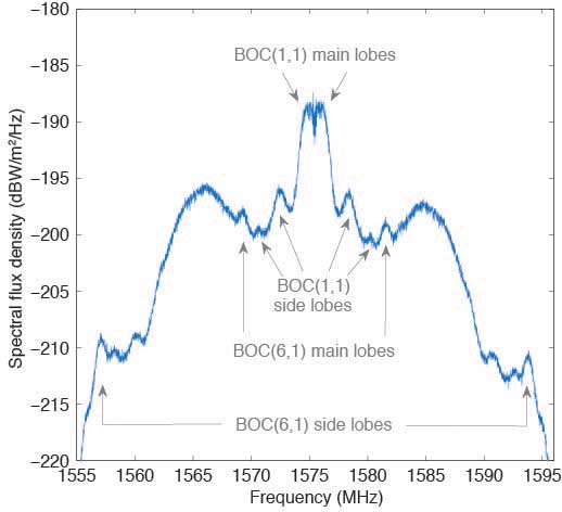
Observations. The German Aerospace Center (DLR) operates a 30-meter dish antenna at its ground station in Weilheim, near Munich, Germany. FIGURE 3 shows the L1 spectrum of SVN74 measured on January 15, 2019. One can clearly see the L1C BOC(1,1) main lobes at 1574 and 1576 MHz as well as the BOC(6,1) main lobes at 1569 and 1581 MHz. Selected side lobes are also indicated.
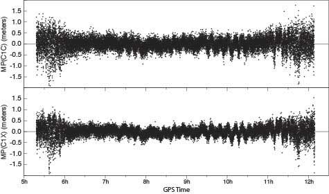
Initially, none of the International GNSS Service network receivers could track the L1C live signal of SVN74, but dedicated firmware versions supporting L1C tracking were soon made available by selected manufacturers. FIGURE 4 shows the multipath linear combination for the L1 C/A-code and the L1C signal tracked with a Javad TRE-G3TH receiver. Reduced measurement noise (multipath plus receiver measurement noise) of the L1C signal can be seen over all elevation angles ranging from about 3 to 83 degrees. (Tracking of the pass began at 4.3 degrees and ended at 3.0 degrees.)
(Image: Authors)
The overall root-mean-square noise of the SVN74 pass shown in Figure 4 is 32 centimeters for the L1 C/A-code signal and 24 centimeters for L1C, that is, a reduction of 25 percent for L1C. Compared to the BPSK modulation of the legacy C/A-code signal, the increased steepness of the TMBOC correlation function offers lower measurement noise for the L1C tracking. In addition, the sensitivity to multipath is reduced.
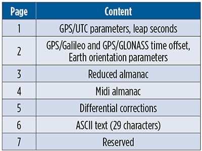
CNAV-2. Together with L1C, the second version of the civil navigation message, namely CNAV-2, is being transmitted. CNAV-2 is composed of three subframes: subframe 1 contains information about the current epoch. Subframe 2 comprises clock and ephemeris data including inter-signal corrections (ISCs). ISCs provide clock corrections for single-frequency users and dual-frequency users utilizing signals other than L1 P(Y) and L2 P(Y). Whereas the essential broadcast ephemeris data in subframe 2 repeat continuously over the validity period of typically two hours, subframe 3 contains pages with alternating content as listed in TABLE 1 (page 41).
Despite a different message layout, most CNAV-2 parameters and their values match those transmitted in the CNAV message of the L2C and L5 signals. Additional parameters comprise the ISCs for the L1C signal. Compared to the LNAV legacy navigation message, CNAV and CNAV-2 utilize an extended set of ephemeris parameters that allow for a smoother orbit representation compared to LNAV. Multi-GNSS applications benefit from the GPS/GNSS time offset (GGTO) parameters included in page 2. In the same page, Earth orientation parameters are provided that are relevant for users of an inertial frame, such as for spaceborne navigation. The CNAV-2 repeat cycle of 18 seconds allows for a faster access to broadcast ephemerides included in subframe 2 compared to LNAV. Compared to CNAV, CNAV-2 furthermore provides a more sophisticated error detection and correction scheme.
As of the beginning of February 2019, only pages 1, 2 and 4 of CNAV-2 subframe 3 are being used. Within a cycle of 144 seconds, page 1, page 2 and six sets of page 4 midi almanac data (each for one individual satellite) are transmitted. The full almanac for 32 satellites is thus transferred in an average of about 13 minutes. The content in these subframes corresponds to that in L2 and L5 CNAV messages. Updates of CNAV-2 are performed in two-hour intervals starting at 01:30. This is the same update scheme as for CNAV but different from LNAV where the two-hour intervals start at 00:00.
Note that some time will pass before enough GPS III satellites are transmitting so that users can fully enjoy the benefits of the new L1C signal.
MANUFACTURERS
Spectral measurements at the Weilheim 30-meter antenna were made with a Rohde & Schwarz FSQ26 vector signal analyzer. Receiver measurements have been collected with a JAVAD GNSS TRE-G3TH receiver running an L1C-capable firmware version.
PETER STEIGENBERGER and OLIVER MONTENBRUCK are scientists at the German Space Operations Center of the German Aerospace Center (DLR). STEFFEN THOELERT is an electrical engineer at DLR’s Institute of Communications and Navigation. RICHARD B. LANGLEY is a professor at the University of New Brunswick and editor of the Innovation column for GPS World magazine.