No audio available for this content.
Precise, Accurate and Multipath-Resistant Distance and Speed Measurements
In this month’s column, we take a look at a short-distance two-way ranging system using a 5.8-GHz carrier to supply not only precise and accurate distance measurements but also complementary measurements of speed.
By Bradley D. Farnsworth, E.J. Kreinar and David W.A. Taylor

THERE IS A LONG HISTORY of determining distances using radio waves with a large number of techniques being developed over the years for positioning, navigation, situational awareness and other purposes.
Of course, we are all familiar with the latest and greatest distance-measuring technology: GPS and its GNSS brethren. The distance to each observable satellite is determined by measuring the time it takes for the radio signal to travel from the transmitting antenna of the satellite to the receiver’s antenna and then, using the speed of light in a vacuum (which is also the speed of radio waves), converting the signal travel time into a distance. Distances can be determined from either the signal’s modulation (the pseudorandom noise codes) or the carrier phase. Both approaches require modeling and estimation to account for various errors or biases.
GPS is an example of one-way ranging. Other systems, notably radar, are two-way systems relying on reflections (passive ranging) or transponders (active ranging) to return a signal to the point of transmission.
Radar was developed during Word War II although radio-ranging technologies and techniques existed before the war started (to measure the height of the ionosphere, for example) and allowed radar’s rapid development and use during the war.
Besides ranging to terrestrial objects, radar has been used extraterrestrially. Independent experiments in the United States and Hungary in 1946 resulted in the first detections of radar reflections from the moon. Radar has been used subsequently to range to other solar system bodies as well.
Also developed during World War II were several radio-based systems for aircraft navigation. An outgrowth of these were the Loran-C and Omega hyperbolic positioning systems. They operated with networks of coordinated transmitters using frequencies at the low end of the radio spectrum. With widespread GPS availability, Omega was shut down in September 1997 followed by the North American Loran-C chains in 2010. Other chains are threatened with closure. However, there is an ongoing debate about bringing Loran-C back to North America in the form of Enhanced Loran (eLoran) as an autonomous backup for GPS. The United Kingdom has already implemented an eLoran network. Among other improvements, eLoran uses range measurements from multiple transmitters to determine position fixes.
The first terrestrial electromagnetic-distance-measurement or EDM device using microwave signals was the Tellurometer. Developed for surveying in 1954, it initially used a 3-GHz carrier modulated by frequencies near 10 MHz and was capable of accurately measuring distances up to at least 50 kilometers (line of sight).
Ranging can be performed with virtually any radio signal, and viable positioning techniques have been developed to use so-called signals of opportunity such as AM, FM and TV signals. And purpose-designed systems have been developed using ultra-wideband and other short-distance radio technologies.
An issue with any radio-based ranging system is multipath where, in addition to a direct line-of-sight signal, interfering signals are received after being reflected off nearby structures. Multipath degrades the system’s achievable precision and accuracy. Better performance can be obtained by using measurements on the signal’s carrier rather than on its modulation, and the higher the carrier frequency, generally the smaller will be the multipath error in the distance measurement. In this month’s column, we take a look at a short-distance two-way ranging system using a 5.8-GHz carrier to supply not only precise and accurate distance measurements but also complementary measurements of speed.
“Innovation” is a regular feature that discusses advances in GPS technology and its applications as well as the fundamentals of GPS positioning. The column is coordinated by Richard Langley of the Department of Geodesy and Geomatics Engineering, University of New Brunswick. He welcomes comments and topic ideas. Email him at lang @ unb.ca.
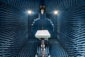
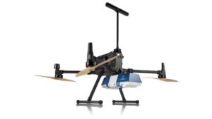
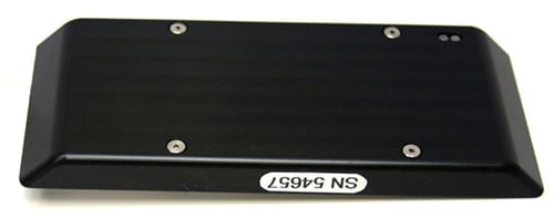
Reliable measurements of distance and speed are a critical aid to integrated positioning and navigation systems. Several different sensor technologies can provide such measurements including a variety of radio frequency (RF) ranging techniques. Previous work by the authors based on round-trip time-of-flight RF ranging using the baseband code phase of direct sequence spread spectrum (DSSS)-modulated signals achieves centimeter-level distance estimation performance. This DSSS ranging implementation approaches the Cramér-Rao lower bound in a benign RF channel (the theoretical lower bound on the variance or corresponding standard deviation of any unbiased estimator of a deterministic parameter — the best we can ever expect to achieve). A distance measuring radio (DMR) produced by our company is shown in FIGURE 1.
Our baseband ranging capability has been demonstrated on a direct conversion radio operating in the unlicensed 5.8-GHz industrial, scientific and medical (ISM) band with approximately 20 MHz RF signal bandwidth, and has been previously implemented in the 2.4 GHz and 915 MHz ISM bands. The system uses an 11-megachip-per-second chipping rate and a symbol rate of about 687 kHz per channel (16 chips per symbol). This method has been implemented with both binary phase-shift keying (BPSK) and quadrature phase-shift keying (QPSK) modulation. The same signal that is used for ranging is also used for data communications. A decentralized asynchronous carrier-sense multiple access with collision avoidance (CSMA/CA) networking layer supports networked operation.
The DMR performs real-time digital signal processing on a Kintex-7 field-programmable gate array (FPGA) baseband processor to compute ranging observables on the received baseband packet structure. A round-trip measurement duration under three milliseconds allows for approximately 350 measurements per second for a single pair of DMRs. Measurements do not require a priori synchronization of the remote radios nor high-performance reference oscillators, as remote oscillator behavior is observed in the ranging operation. The measurement is highly compatible with frequency agility techniques. A system of ranging radios provides networked operation for measurements between multiple platforms.
The primary limitation of DSSS code-phase ranging is degraded accuracy and reliability in challenging multipath environments. This is somewhat mitigated by a “quality factor” observation on the characteristics of the received DSSS baseband signal, which can be used to de-weight or exclude corrupted baseband ranging measurements from an integrated navigation or positioning filter. However, it is desirable to provide a ranging measurement that has improved robustness against multipath corruption in all environments.
Multipath Effects on Carrier Phase
The carrier phase of the DSSS ranging signal in space can be used as an additional ranging measurement. Each 5.8-GHz RF carrier-wave cycle has a length of about 52 millimeters. Phase measurements on the received carrier phase in a round-trip ranging exchange are proportional to the propagation distance of the RF signal over the air. These measurements of the carrier phase can be made precisely, and they are inherently more tolerant to multipath than baseband phase measurements.
Consider a simplified two-ray RF channel model, where there is a direct RF line-of-sight (LOS) path and a multipath (MP) reflection. The two signals will have a phase difference between MP and LOS of θm and an amplitude ratio of MP to LOS of α, which lumps together the attenuation due to the additional path length of the MP signal, the reflection coefficient of the reflecting surface, the difference in antenna gain at the incidence angles and other factors. The received signal will be a superposition of the two signals with a phase difference between this composite and the original LOS of θc. This phase difference is the multipath-induced error on the received carrier phase. The worst-case error will occur when there is a small difference in total path length. In this case, the LOS and MP are inseparable by the DSSS receiver, and the error is bounded by Equation 1. The error is reduced for MP with much longer path length due to both a reduced amplitude coefficient α of the MP signal, as well as separation by the DSSS receiver due to the baseband spreading codes.
![]() (1)
(1)
The multipath carrier-phase error bounds are ±90 degrees for α ≤ 1, which is satisfied when there is an RF LOS signal present. In practice, α is typically much less than 1. For a more practical case of α = 0.1, the maximum carrier-phase error is less than ±6 degrees. At 5.8 GHz RF, ±6 degrees corresponds to about 0.1 millimeters. A plot of this response for various values of α is shown in FIGURE 2.
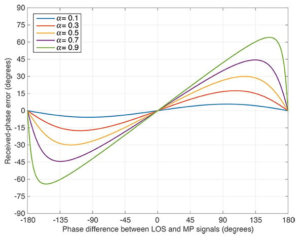
As a physical interpretation, the carrier-phase error goes to zero when there is zero phase difference between LOS and MP signals as the signals happen to be in phase already, and at ±180 degrees where the MP signal is in phase with the LOS signal but with inverted polarity, and serves to reduce the magnitude of the received signal, which is the case in a deep multipath fade. MP signals arrive at a dynamic receiver with an unpredictable distribution of relative phase to the LOS signal due to platform motion. This resistance to multipath is highly desirable for use in an RF ranging system. The following sections will present a ranging method that leverages this useful behavior.
Carrier-Phase Ranging Measurement
Each DMR round-trip ranging exchange consists of transmission and reception of a packet between two cooperating DMR devices, typically termed “originator” and “transponder” with roles determined by software configuration. For baseband ranging, the code phase is computed on the oversampled shape of the DSSS correlator output and exchanged in the round-trip measurement. The number of elapsed baseband clock periods between receive and transmit on the transponder and between transmit and receive on the originator are also observed to compute a round-trip coarse time. These measurements, plus a calibration offset due to cabling and other systematic delays, are used to perform baseband ranging.
Two additional observations are required for carrier-phase ranging: the carrier phase of the received DSSS signal in space and the carrier-frequency offset of the received carrier with respect to the local oscillator on the receiving radio. These observables are exchanged in a round-trip transaction, generating carrier-phase range (CPR), the magnitude of carrier-phase velocity (CPV) and clock-offset measurements. This section will describe the background of the CPR and CPV measurements.
Assuming the communicating DMRs operate with identical carrier frequencies, the round-trip carrier-phase ranging measurement is a function of the RF carrier wavelength λC = c/fC and the received phase on each DMR (φO and φT) in units of radians. The measurement is ambiguous by Namb half-wavelengths, as shown in Equation 2.
![]() (2)
(2)
The frequency offsets measured at each receiver (SO and ST) in units of hertz will reflect the Doppler-based velocity offset between the two receivers, as shown in Equation 3.
![]() (3)
(3)
While the velocity measurement is absolute, the carrier-phase ranging measurement is ambiguous within a half-wavelength in a round-trip measurement. There are several ways to overcome this limitation including using the velocity measurement to “unwrap” sequential carrier-phase observations, using baseband phase measurements to establish absolute offsets, by aiding the measurement with a strapdown inertial measurement unit (IMU) and by other means. The primary error source for carrier-phase ranging in practice is the solution of integer ambiguity, not the actual phase measurements. The quality of the phase measurements becomes the limiting factor when the integer ambiguity is resolved perfectly. An analysis of the Cramér-Rao lower bound (CRLB) for carrier-phase ranging and carrier-frequency velocity measurements along with measured performance is presented in the following section.
Measurement Performance Bounds
The CRLB for estimation of phase and frequency of a sinusoid based on a number of data samples in additive white Gaussian noise has been previously treated in the literature and can be interpreted to provide a best case, lower bound on how well the measurements could perform. The CRLBs for carrier-frequency and phase estimation are computed in terms of the sinusoid’s signal-to-noise ratio, SNR, the number of observed samples of the phase of the signal NS and the sample rate of the measurement system fS.
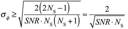
The CRLB for the standard deviation of carrier-phase ranging measurements is presented in Equation 4 in units of radians. In general, the standard deviation of carrier-phase measurements improves with the square root of NS and the square root of SNR.
 (4)
(4)
The CRLB for carrier-phase estimation can be used to compute the CRLB for carrier-phase ranging by scaling each measurement by λC
![]() (5)
(5)
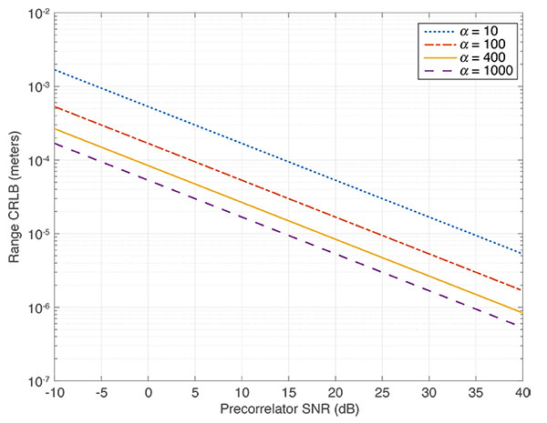
This CRLB can be interpreted for the carrier-phase ranging observable generation process used in this DMR system. NS can be expanded to Equation 6, with NC = 12 chips out of a 16-chip pseudorandom noise code, α = 400 symbols typically tracked (assuming 100 symbrols are consumed in automatic gain control out of a 512-symbol preamble), and fSample/fChip = 44 MHz/11 MHz = 4. [Note different use of the character α here than in the section on multipath.] This gives NS = 400 · 12 · 4 = 19,200 in a typical usable DMR preamble as currently implemented.
![]() (6)
(6)
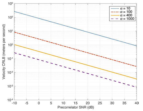
FIGURE 3 shows the CRLB for carrier-phase ranging measurement evaluated over a range of SNR and with a varying number of symbols used in the ranging preamble, with typical α = 400 in the current implementation. Evaluating the phase CRLB at a conservatively low SNR = 10 dB and typical NS = 19,200 on a 5.8-GHz RF carrier yields a lower bound of about 27 micrometers standard deviation for a round-trip carrier-phase ranging measurement.
The CRLB for the standard deviation of carrier-frequency-offset measurements is presented in Equation 7 in units of hertz. In general, the standard deviation of carrier-frequency observation improves with NS3/2 and the square root of SNR.
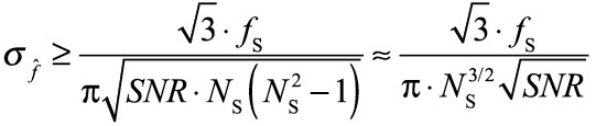 (7)
(7)
The CRLB for carrier-frequency estimation can be used to compute the CRLB for carrier-phase velocity by scaling each measurement by λC to convert to meters per second, and reducing the standard deviation by the square root of 2 due to the two independent phase measurements being conducted in the round-trip experiment as shown in Equation 8.
![]() (8)
(8)
Evaluating the round-trip carrier-phase velocity CRLB at a conservatively low SNR = 10 dB and typical NS = 19,200 on a 5.8-GHz RF carrier yields a lower bound of about 10 centimeters per second velocity standard deviation. FIGURE 4 shows the CRLB for velocity measurement evaluated over a range of SNR and with varying number of symbols used in the ranging preamble.
These CRLB levels predict that excellent CPR with precision much better than millimeter level and CPV precision much better than a meter per second should be achievable with the designed system assuming a perfect carrier-frequency generation circuit operating in additive white Gaussian noise. The practical limiting factor for these measurements at high SNR is typically the phase-noise performance of the reference oscillators themselves.
Measurement Results
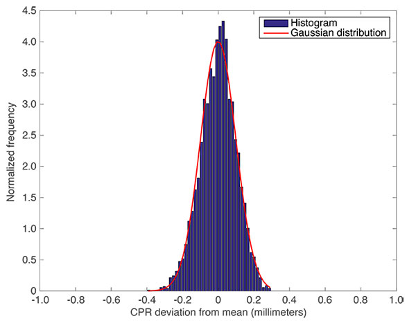
CPR measurements have been implemented in our DMRs and tested in a variety of environments. In a static data collection, CPR demonstrates a stationary precision of approximately 0.1 millimeters at one sigma as shown in the histogram in FIGURE 5. The red line indicates the best-fit to a Gaussian curve of the measurement data, showing very well behaved data.
A static collection of CPV measurements demonstrates a precision of approximately 15 centimeters per second at one sigma as shown in the histogram of CPV data in FIGURE 6, which also has the best fit Gaussian distribution overlaid. The performance of these measurements approaches the CRLB.

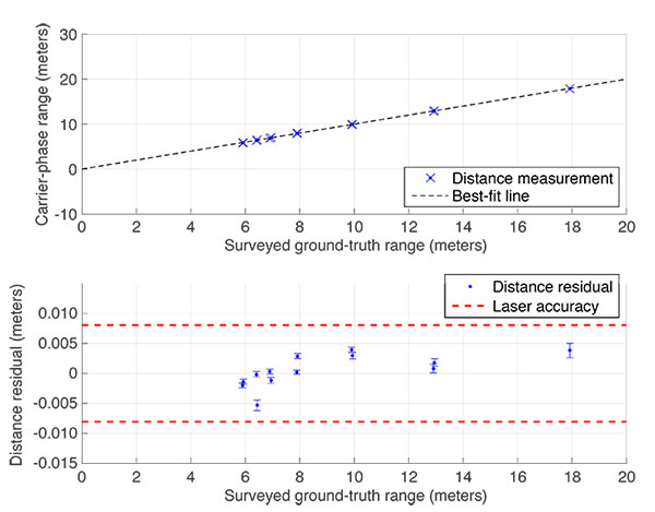
To further quantify the accuracy of CPR, a test was conducted comparing CPR to the distance measured by a survey-grade total station laser rangefinder. The transponding radio was mounted on a tripod and moved to varying distances away from the originating radio, which was located near the total station. FIGURE 7 shows the distance-measurement results. The blue dots are the baseband distance measurements and the red dots are the unwrapped carrier-phase range distance measurements. The mean distance and scatter within each stationary period were used to evaluate the precision and accuracy of CPR versus the total station rangefinder values.
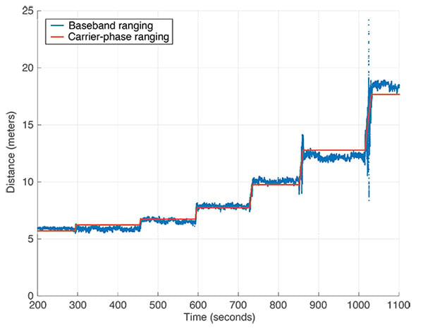
FIGURE 8 shows the outcome of the laser-based total station ground-truth validation of the carrier-phase distance measuring performance in an outdoor LOS environment. The red lines indicate the ±8 millimeter experimental accuracy of the laser ground-truth test setup. The error from each surveyed point is within the uncertainty of the test, with an experimental precision of 0.6 millimeters at one sigma indicated by the vertical error bars on each data point.
System Integration
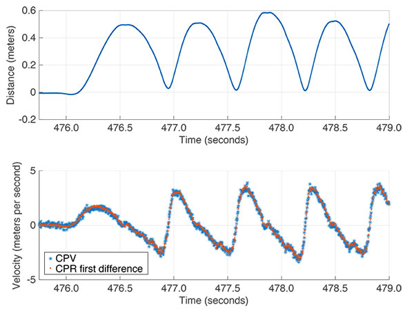
CPR and CPV measurements have been successfully integrated into a pedestrian tracking dual boot-mounted inertial system. In this configuration, one industrial-grade microelectromechanical systems IMU operating at 400 Hz (three-axis accelerometer, three-axis gyro and three-axis magnetic compass) is mounted on the heel of each boot, and a DMR with CPR/CPV capability is attached to the medial side of each boot. The DMRs perform inter-boot ranging and velocity measurements at 360 Hz throughout system operation. The walking motion generates a very high-dynamic, high-multipath environment that is challenging for RF systems.
FIGURE 9 shows four strides of walking data collected in this configuration. Periodic walking motion is clearly visible on CPR and CPV as the range between boots increases up to 0.6 meters at the extents of strides and passes near zero during foot crossings. CPV measurements are internally consistent with CPR. The first difference of CPR is equivalent to the independent Doppler-based CPV measurement. A significant benefit of the CPV measurement as opposed to the first difference of CPR is that CPV is an absolute measurement with no integer ambiguity.
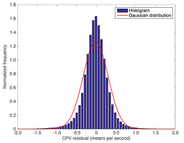
For this system, IMU data is integrated using both interpreted zero-velocity updates (ZUPTs) and ranging measurements to determine dead-reckoning motion of each individual boot. The high-precision, multipath-tolerant CPR and CPV measurements are used to constrain inter-boot position and velocity in a centralized extended Kalman filter (CEKF). CPR and CPV residuals from the CEKF are shown in FIGURE 10 and FIGURE 11, representing measurement accuracy in a challenging, high-dynamic environment. All system errors including antenna phase response, integrated IMU errors, and others are included in these histograms, so the true CPR and CPV measurement errors are likely significantly lower, even for this high-multipath environment. This is why we believe our results are a good estimate of the system’s accuracy capability.
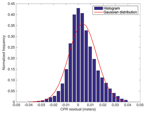
While the overall CPR measurement accuracy of about 11 millimeters is two orders of magnitude worse than the stationary measurement precision of 0.1 millimeters, it should be noted that this includes all measurement biases in the system and various error sources.
CPV achieves an in-system measurement accuracy of 0.31 meters per second, which is approximately a factor of two degraded from the stationary, LOS collection (0.15 meters per second). In this sense, CPV is shown to be an extremely robust measurement in the presence of multipath and non-ideal antenna patterns throughout actual walking motion.
Conclusions
This article presents a new method to perform highly precise, accurate and multipath-resistant measurements of distance and velocity using a small portable radio. Measurements that are as accurate as a laser require only milliseconds to complete and are insensitive to multipath interference. This opens up a wide range of applicability as an aiding sensor to integrated navigation systems. Performance has been demonstrated in the high-dynamic and high-multipath environment between the boots of a walking pedestrian, and similar performance is expected in industrial and military applications. By employing a conventional communications link, measurements of CPR and CPV should be scalable to longer distances with the availability of the measurements roughly comparable to the availability of the communications link.
CPR and CPV achieve stand-alone measurement precision of much better than 1 millimeter standard deviation, and about 15 centimeters per second velocity respectively at a rate of hundreds of measurements per second. In-system performance of CPR and CPV measurement residuals demonstrates 1-centimeter CPR accuracy and 30 centimeters per second CPV accuracy. The measurements presented in this article are typically 100 times more precise than typical baseband round-trip RF measurements in a similarly challenging RF environment.
Acknowledgments
The work described in this article was sponsored by ENSCO Inc.
Manufacturers
The distance measuring radio is manufactured by ENSCO Inc. The inertial measurement unit used in the boot test was a Memsense LLC model H3, while the total station used for calibration was a Leica Geosystems AG model TS30.
BRADLEY D. FARNSWORTH is the chief engineer for positioning, navigation and timing (PNT) at ENSCO Inc., Springfield, Va. He holds several U.S. patents and has expertise in real-time signal processing, autonomous systems and mixed-signal design. He received his B.S. summa cum laude and M.S. degrees in electrical engineering from Case Western Reserve University, Cleveland, Ohio.
E.J. KREINAR is with ENSCO Inc. and holds B.S. and M.S. degrees in electrical engineering from Case Western Reserve University. He has expertise in optimal estimation using Kalman filters, real-time signal processing and autonomous systems.
DAVID W.A. TAYLOR is the director of technology development and business area lead for PNT at ENSCO Inc., where he leads R&D programs developing sensors and systems for national security applications. He holds several U.S. patents and is an expert in GPS-denied navigation technologies. Taylor holds a B.S. in physics from Rhodes College, Memphis, Tenn. and a Ph.D. in geophysics from Virginia Polytechnic Institute and State University (Virginia Tech), Blacksburg, Va.
FURTHER READING
- Authors’ Conference Paper on which the Article is Based
“Precise, Accurate, and Multipath-Resistant Networked Round-Trip Carrier Phase RF Ranging” by B.D. Farnsworth, E.J. Kreiner and D.W.A. Taylor in Proceedings of ITM 2015, the 2015 International Technical Meeting of The Institute of Navigation, Dana Point, Calif. January 26–28, 2015, pp. 651–656.
- Radio Frequency Ranging
“Where Are We? Positioning in Challenging Environments Using Ultra-Wideband Sensor Networks” by Z. Koppanyi, C.K. Toth and D.A. Grejner-Brzezinska in GPS World, Vol. 26, No. 3, March 2015, pp. 44–49.
“Hybrid Positioning: A Prototype System for Navigation in GPS-Challenged Environments” by C. Rizos, D.A. Grejner-Brzezinska, C.K. Toth, A.G. Dempster, Y. Li, N. Politi, J. Barnes, H. Sun and L. Li in GPS World, Vol. 21, No. 3, March 2010, pp. 42–47.
RF Ranging for Location Awareness by S.M. Lanzisera and K. Pister, Technical Report No. UCB/EECS-2009-69, Dept. of Electrical Engineering and Computer Sciences, University of California at Berkeley, Berkeley, Calif., May 19, 2009.
“Opportunistic Navigation: Finding Your Way with AM Signals of Opportunity” by J. McEllroy, J.F. Raquet and M.A. Temple in GPS World, Vol. 18, No. 7, July 2007, pp. 44–49.
“GPS + LORAN-C: Performance Analysis of an Integrated Tracking System” by J. Carroll in GPS World, Vol. 17, No. 7, July 2006, pp. 40–47.
“Prime Time Positioning: Using Broadcast TV Signals to Fill GPS Acquisition Gaps” by M. Martone and J. Metzler in GPS World, Vol. 16, No. 9, September 2005, pp. 52–60.
- Direct Sequence Spread Spectrum Radio Frequency Ranging
“High-Precision 2.4 GHz DSSS RF Ranging” by B.D. Farnsworth and D.W.A. Taylor in Proceedings of ITM 2011, the 2011 International Technical Meeting of The Institute of Navigation, San Diego, Calif., January 24–26, 2011, pp. 178–183.
“High Precision Narrow-Band RF Ranging” by B.D. Farnsworth and D.W.A. Taylor in Proceedings of ITM 2010, the 2010 International Technical Meeting of The Institute of Navigation, San Diego, Calif., January 25–27, 2010, pp. 161–166.
- Estimating Phase and Frequency of Noisy Signals
Phase and Frequency Estimation: High-Accuracy and Low-Complexity Techniques by Y. Liao, Master’s thesis, Dept. of Electrical and Computer Engineering, Worcester Polytechnic Institute, Worcester, Mass., May 2011.
Equation images: Bradley D. Farnsworth, E.J. Kreinar and David W.A. Taylor