No audio available for this content.
A new miniature atomic clock offers improvements to temperature sensitivity and long-term drift, which correlate to longer holdover durations. Features important to mobile applications —warm-up characteristics, gravity sensitivity, and shock and vibration — as well as new 1 pulse-per-second (PPP) input and output signals are highlighted.
By William Krzewick, Jamie Mitchell, John Bollettiero, Peter Cash, Kevin Wellwood, Igor Kosvin and Larry Zanca
The miniature atomic clock (MAC) was developed out of the same size and power-reducing technology, known as coherent population trapping (CPT), as the venerable chip-scale atomic clock (CSAC). By implementing low-power lasers as opposed to traditional lamp designs, this technology allows for unparalleled performance versus power consumption in the commercial oscillator domain.
Since its initial release in 2009, the MAC has been well-suited for telecom applications as a holdover reference oscillator in GNSS-denied environments. Now, with advances in field-programmable gate array (FPGA) design, signal processing and electronics miniaturization, and by leveraging more than 40 years of atomic clock design at Microchip Technology, the next generation MAC is designed to meet a variety of applications with demanding mission scenarios.
In this article, we discuss improvements to temperature sensitivity and long-term drift, which correlate to longer holdover durations. We also discuss warm-up characteristics, gravity (g)-sensitivity, and shock and vibration, which are important for mobile applications. Finally, several new features will be introduced including a 1 pulse-per-second (1PPP) input and output signal.
INTRODUCTION
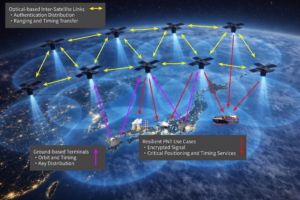
Low-drift performance over time and frequency stability during temperature changes have enabled small atomic oscillators to maintain precise time and frequency in the absence of a primary reference such as GNSS. The MAC-SA5X rubidium (Rb) miniature atomic clock has advanced the design of the legacy MAC-SA.3Xm with a wider operating temperature range, additional features and improvement in frequency drift and temperature stability to enable longer holdover durations. Measuring 2 × 2 × 0.72 inches (5.08 × 5.08 × 1.83 centimeters), it is designed for size and power-constrained applications that require atomic clock performance.
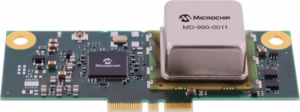
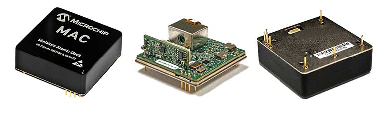
FIGURE 1 shows exterior and interior views of the MAC, while FIGURE 2 is a block diagram of the clock. The vertical-cavity surface-emitting laser (VCSEL) with thermoelectric cooler (TEC) generates the light source at the appropriate wavelength. The laser light is directed into the resonance cell to stimulate the Rb atoms. Use of a VCSEL, as opposed to the traditional lamp design, results in a relatively low-power, small-form-factor package while eliminating frequency jumps and preserving short-term stability. The new TEC enables fast temperature response, increased temperature set-point resolution, and a larger temperature range.

The temperature-compensated crystal oscillator (TCXO) drives an FPGA-based direct digital synthesizer (DDS) for higher accuracy with minimal board space intrusion, differential signaling and additional power isolation. Linear microwave control, which has direct impact on frequency stability as measured by the Allan deviation (ADEV), lock times and temperature compensation, is a key improvement.
The resonance cell subassembly contains the Rb gas mixture. It is surrounded by an oven with C-field (static magnetic field) coil necessary for controlling the temperature and magnetic field, respectively, of the Rb atoms. Dual magnetic shields mitigate the effects of external magnetic fields. The photodiode printed-circuit-board assembly detects CPT resonance of the clock. The resonator is fundamentally unchanged and therefore not expected to impact the quality factor, Q, of the oscillator.
The signal-to-noise ratio (SNR) of the CPT signal, on the other hand, has improved thanks to the updated control electronics design, faster servo-loop algorithms and use of lower noise electronics. This is evident in the less noisy clock transition for the MAC-SA5X (orange trace in FIGURE 3) versus the predecessor (black trace). Because the 1-second ADEV is proportional to 1/(Q×SNR), the short-term stability is improved in the new design.

PERFORMANCE
This next generation of the rubidium atomic clock leverages substantial improvements in both hardware and software. These improvements, coupled with more than a decade of experience in practical CPT technology, have allowed for significant insight into physics behavior and interrogation techniques. This has resulted in improvements to key performance parameters such as temperature range, stability, retrace and lock times. These metrics will be reviewed in the following sections by comparing data from a sample of pre-production engineering units.
ADEV. Short-term frequency stability of the oscillators is represented in FIGURE 4 as an ADEV measurement. The MAC-SA5X has two performance classifications: The SA53 is the base-performance (red dots) and the SA55 is the high-performance (red squares). The MAC-SA55 has a 1-second integration period, tau (τ) = 1 second, ADEV requirement of less than 3 × 10-11, that follows a 1/√τ behavior to τ = 1000 seconds. ADEV rises at 105 seconds to accommodate the mid-/long-term frequency drift of the oscillator, with a generous margin. The base-performance version MAC-SA53 has a looser ADEV specification of less than 5 × 10-11 at 1 second that follows a 1/√τ behavior to 100 seconds.
On average (dashed line), the sample units had a 1-second ADEV of about 1.2 × 10⁻¹¹. A narrow grey line represents the average values of the data set plus two standard deviations, and the orange line represents a sample unit that closely mirrored the average performance (limited sample size of five for long-term testing).
Two notes on Figure 4 are worth mentioning: The standard deviation line has a larger spread from average as the observation interval increases and a small (~2 × 10-13) bump exists in the measurement at 400 seconds. The former is due to increased measurement noise as there are simply fewer data points for longer τ. The latter is believed to be a result of the heating, ventilation and air conditioning (HVAC) system in the laboratory as it cycled. All MACs are compensated to reduce temperature effects, as will be discussed later. However, these units were not compensated at the time of testing and were more susceptible to HVAC temperature effects compared to full-production units.

Aging. Long-term frequency drift (monthly aging rate) of the MAC has a requirement of 1 × 10⁻¹⁰ per month and 5 × 10-11 per month for the SA53 and SA55 variants, respectively. It is important to note that the majority of sample units fall well within the tighter 5 × 10-11 per month requirement and accordingly affect the average mid-/long-term stability in the ADEV plot. Future production units that only meet the baseline SA53 performance could have inferior stability beyond τ = 100 seconds, compared to our sample data.
TDEV. The time stability of the phase is represented in FIGURE 5 as a time deviation (TDEV) measurement. This type of test is important to compare oscillators, since it gives an estimation of time error accumulation due to only the free-running oscillator itself by removing time or frequency errors at the beginning of the test. The graph uses the same color scheme as the ADEV plot to indicate average data (dashed line), average plus two standard deviation data (thin line) and a sample unit as an orange trace.

Based on the required stability performance of the SA55, the time error after three days for a free-running oscillator is predicted to be less than 650 nanoseconds. For the measured units, the MACs had a TDEV of about 230 nanoseconds at τ = three days, due to the long-term drift performance of our samples.
Phase Noise. Phase noise for the MAC has two classifications: base performance and high performance over the range 1 Hz to 10 kHz.
Average phase noise data is well below the requirements, for our samples.
Temperature Effects. As a small Rb oscillator, the MAC inherently has low sensitivity to environmental temperature perturbations compared to most commercial quartz oscillators. To further improve performance, each MAC is characterized and compensated with a high-order polynomial fit of temperature effects to reduce peak-to-peak frequency changes below 5 × 10-11 over a wide operating range. The SA53 has a two times relaxation for this requirement.
Retrace. Retrace specifications are provided to indicate the expected frequency change of an oscillator due to that oscillator being powered off and back on again. The MAC retrace test is defined as follows:
- The MAC is powered on, and its frequency offset (from nominal) is measured after 24 hours.
- Power is removed for 48 hours.
- Power is turned back on, and its frequency offset is measured again after 12 hours.
- The delta frequency between the two measurements is calculated to be within ±5 × 10-11.
A test verified the specification of ±5 × 10-11 after 12 hours.
For this test, however, we did not wait 12 hours to measure the retrace frequency change. Instead, we began measuring immediately after power was turned back on. The measured data from sample SN00011 is indicative of typical performance and shows how the MAC retrace frequency delta is well within ±1 × 10-11. This unit had a slightly positive delta and meets the retrace requirement in minutes — far sooner than the modest 12-hour specification.
The sample units as a whole performed similarly to the sample SN00011.
Warm-up Time. Defined as the time to reach atomic lock, warm-up time is the point at which atomic resonance is attained and the short-term stability performance of the oscillator will be achieved. Test average and standard deviation data is well within the requirement of 8 minutes at temperatures greater than –10°C. At colder temperatures, the requirement is 12 minutes.
Typical performance is about four minutes to achieve lock at a starting temperature of 25°C. This has been a major design focus; all MACs are designed and tested to quickly achieve lock at all temperatures.
Power Consumption. Average power consumption in a 25°C environment is about 6 W. Warmer environments reduce the power consumption, due to less required heating of the resonance cell to achieve the appropriate temperature.
1PPS Disciplining. A 1-Hz (1PPS) input and output signal are new features for the MAC. The 1PPS output is derived directly from the TCXO, and its stability performance is therefore tied to the RF output performance. The 1PPS input accepts a reference signal from a primary reference clock to calibrate the MAC’s 1PPS (and RF) output. The algorithm will simultaneously steer the phase and frequency to that of the external reference (1PPS input), ultimately achieving accuracies of less than 1 nanosecond and 1 × 10-13, respectively. This feature is quite useful for applications where absolute frequency or phase errors need to be minimized and is similar to the function available on the CSAC.
The MAC can quickly calibrate its RF output by turning on the 1PPS disciplining feature to correct a 1.4 × 10⁻⁸ frequency error in minutes. A user can adjust the disciplining time constant to accommodate for noisier 1PPS input signals, if necessary.
g-Sensitivity Testing. Vibration and g-sensitivity testing was conducted. Static acceleration effects, such as a “tipover” test, on atomic clocks are minimal, and they exhibit a sensitivity of several parts per trillion per g. The MAC significantly outperformed a commercial oven-controlled crystal oscillator or OCXO. This type of performance is important for applications where the equipment is placed on its side, for instance.
Unlike static acceleration, effects due to random vibration profiles are determined mostly by the TCXO and will adversely affect the performance. Preliminary testing of the MAC has shown an effective sensitivity of several parts per billion per g. TABLE 1 describes the profile used to test the MAC from “MIL-STD-810, Fig. 514.7E-1, Category 24.” The profile was applied to all three axes tested.

The g-sensitivity may be calculated from the dynamic phase-noise measurement. The total effective g-sensitivity was determined by taking the magnitude due to the random vibration profile applied in all three axes.
The total effective g-sensitivity due to the random vibration profile is about 2.4 × 10⁻⁹ per g. Results of the worst-case sensitivity are summarized in TABLE 2.
Table 1. Random Vibration Profile Expressed as Power Spectral Density (PSD). (Data: Microchip; Graphic: GPS World)
SUMMARY
Based on the CPT method of interrogation, a commercial miniaturized rubidium atomic clock has been developed with a wider operating temperature of –40 to +75°C and improved performance over its predecessor MAC-SA.3Xm. New features, such as the 1PPS input, allow users to connect a GNSS-derived signal to calibrate the clock and then maintain timing during GNSS-outages for longer durations thanks to improvements in stability performance. Retrace measurements of ±1 × 10-11, temperature stability of less than 5 × 10-11 and fast/consistent warm-up times along with the small size and power afforded by CPT technology enable a variety of mobile applications.
ACKNOWLEDGEMENT
This article is based on the paper “A Next-Generation, Miniaturized Rb Atomic Clock Reference for Mobile, GNSS-Denied Environments” presented at ION ITM 2020, the International Technical Meeting of The Institute of Navigation, held in San Diego, California, Jan. 21–24, 2020.
At Microchip Technology, WILLIAM KRZEWICK is the product line manager, JAMIE MITCHELL is the manager of engineering, JOHN BOLLETTIERO is an associate engineer, PETER CASH is the associate director of clock products, KEVIN WELLWOOD is the manager of software engineering, IGOR KOSVIN is the principal engineer of electrical engineering and LARRY ZANCA is the principal engineer of mechanical engineering.