Simplifying the lidar survey requires unity of hardware and software

From OxTS
OxTS manufactures inertial navigation systems (INS) and proprietary software on which survey professionals have come to rely. Our devices, the Survey+ and the xNAV650, output highly accurate position, heading and pitch/roll measurements. An advanced navigation engine combines streams of data from onboard inertial measurement units (IMUs) and GNSS receivers. This data can then be used in a multitude of applications including lidar survey, mobile mapping and open road positioning.
Surveying, especially with a lidar sensor, can be a complicated art. There are many factors to consider even before you begin. However, system manufacturers involved in the survey industry, such as OxTS, are taking steps to simplify lidar survey.
The end goal for many lidar surveyors is to create an accurate point cloud. However, to produce the best possible results, the hardware and software involved must be working together in unison.
Hardware = lidar sensor and INS
Software = georeferencing, post-process and configuration
In this article, we have picked out a few of our favorite developments on the topic of simplifying lidar survey.
Research and Development
OxTS invests substantially in research and development to ensure that our hardware and software developments meet the ever-evolving demands of the survey industry. Many of the improvements generally center around improving accuracy, clarity of results and user experience. However, general industry demands also drive some development.
For example, the increasing use of drones in surveying has increased demand for smaller and lighter INS hardware. Whilst developing smaller and lighter hardware is therefore important it cannot be to the detriment of reliability and accuracy. The xNAV650 was born from this industry demand.
Although development of the xNAV650 was primarily driven by the needs of the survey industry (smaller/lighter hardware), other improvements OxTS has made to the software portfolio has focused on improving user experience.

xNAV650 and Survey+ inertial navigation systems. (Photo: OxTS)
Precision Time Protocol (PTP)
One of the major advances in OxTS INS technology over the past 12 months is PTP. The drive to include PTP capability on all OxTS Survey INS devices was the intention to help surveyors simplify the lidar survey set-up process.
When using compatible lidar sensors, such as those from Hesai and Ouster with an OxTS INS, surveyors no longer need to build complex wiring solutions. A simple ethernet ‘plug-and-play’ process is all that is required.
The images below show a traditional PPS wiring set-up vs PTP:
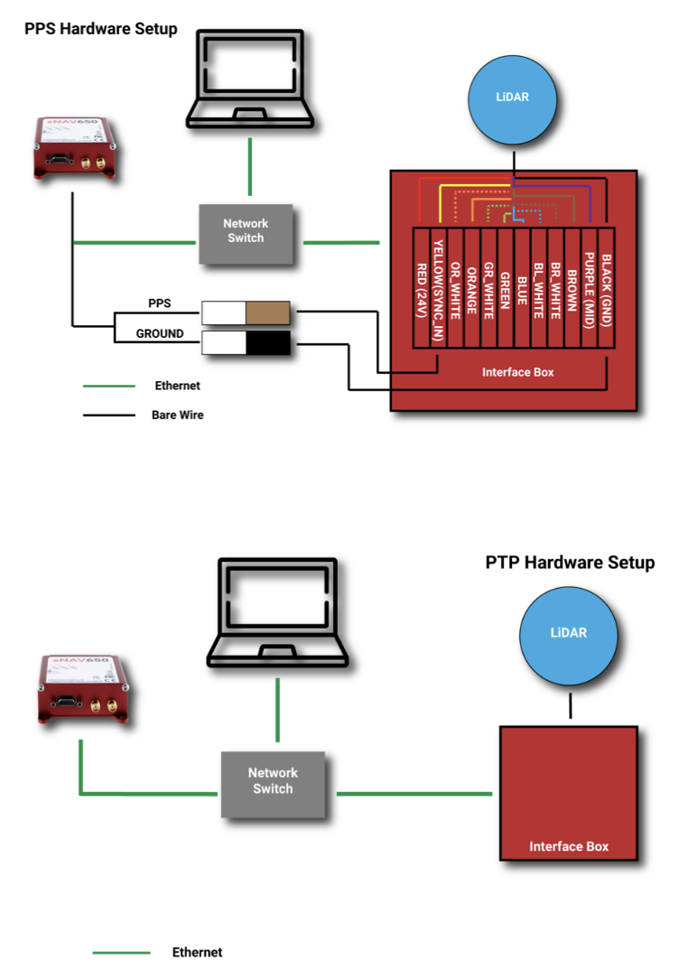
A traditional PPS wiring set-up vs PTP. (Image: OxTS)
Software
To get the desired outcome, an accurate georeferenced point cloud, from any lidar survey in a timely manner the software must be simple and straightforward to use. As the saying goes “complexity is the enemy of execution,” and this is what drives software development at OxTS.
Once the lidar and INS are plugged in and ready to survey, configuration should be straightforward. A simple configuration wizard, such as the one available in NAVsuite (OxTS’ complimentary software toolbox) should structure the set-up process so that nothing is missed.

NAVconfig – OxTS’ INS configuration software. (Image: OxTS)
The latest NAVsuite update (version 3.3) included a new PTP graphical user interface (GUI) to simplify survey set-up even further.
Other tools are included within NAVsuite that allow users to analyze, troubleshoot and post-process their INS data. Read the NAVsuite for Survey and Mapping infosheet to find out more about these.
OxTS Georeferencer

OxTS Georeferencer. (Image: OxTS)
Since its launch approximately two years ago, OxTS Georeferencer has gone through some major changes. The first version included compatibility with the Velodyne VLP-16 lidar sensor. This meant that users of the VLP-16 had a quick and simple way to georeference the lidar data.
Over the course of the next 24 months, multiple new sensors have been introduced. Sensors from Hesai, Ouster, Livox and new Velodyne devices are now available, giving users more choice than ever before when it comes to choosing the hardware to do their job. Visit the OxTS Georeferencer product page for a complete list of available sensors.
Furthermore, as well as the integration of new sensors, we have introduced a raft of new features to improve the user experience for professional lidar surveyors. These include:
- a 3D hardware setup viewer to enable quick and intuitive survey configuration
- multiple processing options that allow users to view and process only the areas of the point cloud that are of interest therefore minimizing the data size
- the ability for users to process data in a range of coordinate systems including, local coordinates, ECEF, LLA (latitude, longitude and altitude)
- processing advances that enable users to process data faster than ever before.
Data-Driven Boresight Calibration
One of the most challenging parts of the lidar survey set-up process is aligning the coordinate frames of the lidar and INS devices. Failure to align these with sufficient accuracy can lead to blurring and double-vision in point clouds.
Many surveyors try to do this by eye, or by developing expensive CAD models, however there is a simpler, quicker and more cost-effective way – using data.
Built into OxTS’ lidar georeferencing software OxTS Georeferencer, there is an optional boresight calibration tool. It requires the surveyor to survey two static “targets” (see the images below) from multiple distances and angles. The data is then calibrated, and the angle displacement calculated to a tenth of a degree.
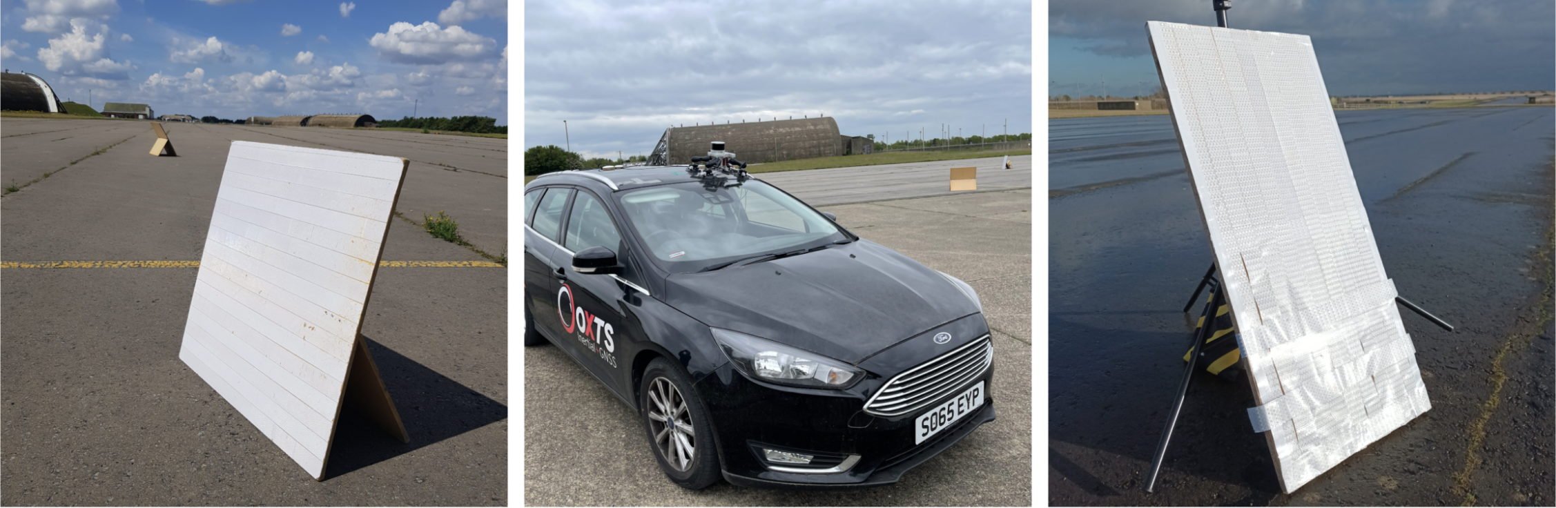
OxTS Georeferencer includes an optional boresight calibration tool. (Photos: OxTS)
Once the initial boresight calibration has taken place, if the setup is not altered in any way, the coordinate frame alignment will be valid for any future survey.
The Future
In the coming weeks and months, the development of new hardware and software features will further streamline the survey process.


About the Author: Tracy Cozzens
Senior Editor Tracy Cozzens joined GPS World magazine in 2006. She also is editor of GPS World’s newsletters and the sister website Geospatial Solutions. She has worked in government, for non-profits, and in corporate communications, editing a variety of publications for audiences ranging from federal government contractors to teachers.


Subscribe to GPS World
If you enjoyed this article, subscribe to GPS World to receive more articles just like it.


Follow Us