Inside the box: GNSS antenna designs


Sea level changes are monitored using a VeraChoke antenna at a GNSS observing station in Canada. (Image: Natural Resources Canada)
All antennas for global navigation satellite systems (GNSS) receivers serve the same fundamental function: to capture, filter, amplify the observed signals and relay them to the receiver. For high precision applications, certain design techniques allow for more accurate signal acquisition. These techniques involve the three main components of a GNSS antenna: the radiating element, additional ground plane, and the radio frequency (RF) frontend also called low noise amplifier (LNA).
Ceramic Patch Antennas
First, we will look at the antenna radiating element. Let us look at a common style of antenna that you might see in a surveying rover, a “patch” and associated ground plane. The patch, typically a metalized square or disk printed on a dielectric substrate, set in the middle of the ground plane, can have one or more feed points connecte to the RF frontend. For certain applications we may use only one feed point, which yields a narrow bandwidth; in other words, the circular polarization bandwidth of a single feed patch is very narrow. Single feed patches are then generally used for GPS L1-only applications. With two or more feed points, the circular polarization of the antenna is drastically improved over wider bandwidth. Putting it simply, for a two feed point antenna, the orthogonal currents flowing on the metalized surface of the patch are detected independently in both axes, one feed for each axis. The two signals are then combined using a 90 degrees hybrid coupler to reconstruct the GNSS information from the satellite. To cover multiple bands, such as L1 and L2, or L1 and L5, multiple patches can be stacked together.
Precision and Helicals
High performance dual feed patch antennas typically deliver phase information error of about 10 mm, though that does not mean you cannot achieve any higher. Depending on design specifics, other antenna technologies can achieve even higher precision. Helical antennas, another common design, yield a precision of at least 5 mm. They are taller than patch antennas, with a coil of four metallic elements pointing upwards. A key advantage is that helical antennas are less impacted by the absence of ground plane and still mitigate multipath interference in such a situation. Although being exceptionally light, a clear disadvantage of helical antennas is their height. However, a reduced height version of the technology is being developed that performs on par to the original technology.
Higher Accuracy
The key to even higher precision, down to an accuracy of less than 1 mm, is in the design of the individual components of the antenna element. Traditionally, the highest performing elements are quite sophisticated and difficult to manufacture, therefore they are quite expensive, and can be in limited supply. For certain legacy geodetic antennas, typically built into a choke ring, the element alone might cost several thousand dollars. We have taken inspiration from these designs and developed variations that have been able to deliver higher performance at a much lower cost.
Crossed Dipole Antennas
One of those approaches is an element that uses two wide band crossed dipoles mounted at 90 degrees from each other. The dipoles are connected directly to the RF frontend. Again, we combine two linearly polarized components through a 90 degrees phase coupler to reconstruct the right hand circular signal. Using RF engineering techniques these dipoles are coupled to other antenna element components, such as metalized “petals”, to improve or enhance performance in various ways. These enhancements include a wider bandwidth enabling the coverage of the entire GNSS spectrum, a more favorable radiation pattern; high low-elevation gain, and higher gain at zenith. This technology is the basis of our VeroStar, VeraPhase, and VeraChoke lines of antennas.
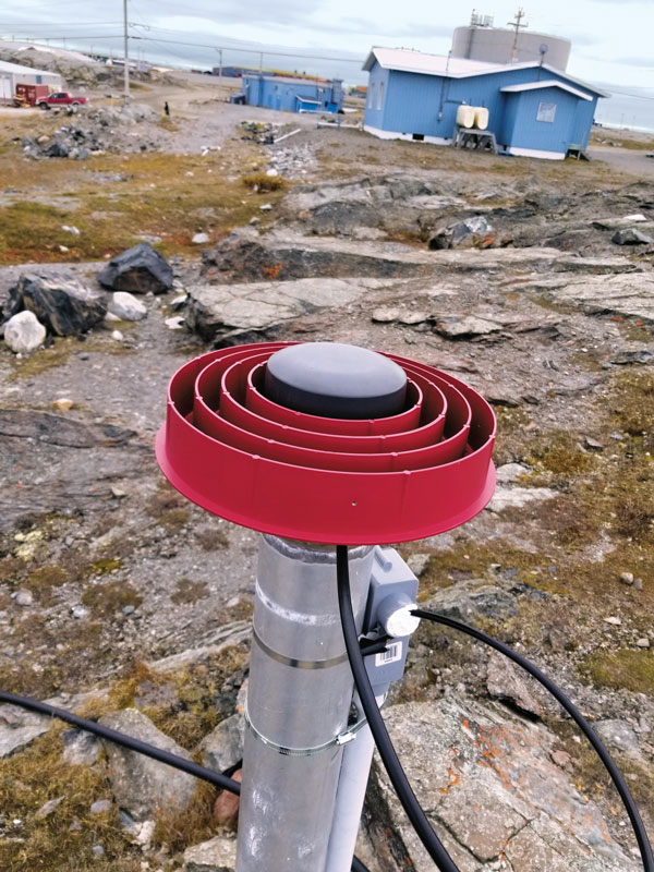
The rate of crustal motion is estimated using data collected by a VeraChoke antenna at a GNSS observing station at Rankin Inlet, Canada. (Image: Natural Resources Canada)
Ground plane and ChokeRings
Two additional elements that enhance certain antennas’ performance are ground planes and choke rings. An antenna does not necessarily need an external ground plane, a prime example being helical antennas. However, some antennas, such as patches, perform optimally with one. A choke ring is often used to attenuate signals from the horizon or below it, which are generally unwanted signals as they are typically due to multipath. To an extent, the concentric rings of a choke ring create a highly resistive surface for any low-elevation signals. Beyond the physical and electrical design aspects of the antenna, remaining interference from multipath may be mitigated algorithmically in the receiver.
RF Frontend
Coming after the radiating element is the RF frontend, another key component of high precision antennas. RF frontends include amplifier stages — which, as the name implies, amplify signals — and filters, such as ceramic or surface acoustic wave (SAW) filters, which reduce out-of-band signals while allowing in-band signals through. The GNSS signals from space are very weak and need to be amplified, often by a factor of 1,000 or more. There are two techniques for using filters: pre-filtering and in-line filtering. Pre-filters come before the first amplifier stage and prevent in band harmonics. In today’s congested RF spectrum, nearby signals or their harmonics can affect the RF frontend to the point that a non-prefiltered antenna will put the whole GNSS system at risk. A pre-filter mitigates this, but there is no free ride. Including a pre-filter in the RF frontend slightly increases the noise figure, which will slightly reduce the receiver signal-to-noise ratio (C/N0). However, a pre-filtered antenna will ensure the GNSS system to continue to operate in the presence of interference. Filters may also be applied between amplifier stages to further attenuate out-of-band interference.
In conclusion, a GNSS antenna is the optimal sum of three components: a well-designed radiating element, carefully selected external ground plane, and a high performing RF frontend. Technologies and models are available for every specific application that may arise. For example, patches are good general purpose antennas with a low-profile, helicals are lightweight and operate well without a ground plane, and crossed dipole antennas are ideal full GNSS rover and base station applications.


About the Author: Joseph Botros
Joseph Botros is the Senior Antenna & RF Designer for Tallysman Wireless


Subscribe to GPS World
If you enjoyed this article, subscribe to GPS World to receive more articles just like it.


Follow Us